


 Very often we forget to switch off the connected peripherals like monitor, scanner and printer while switching off our PC. This leads to needless energy consumption and possible shortening of the life of the peripheral. PCs with an ATX switch-mode power supply (SMPS) unit are not provided with a mains switch outlet. It is therefore not possible to achieve automatic switching (on/off) of peripheral units with the computer power switch. Here is a simple PC power manager that turns the connected peripherals on/off along with your PC.
PC power manager circuit
It consists of a regulated power supply, a simple USB interface and two electromagnetic relays used as power switches.
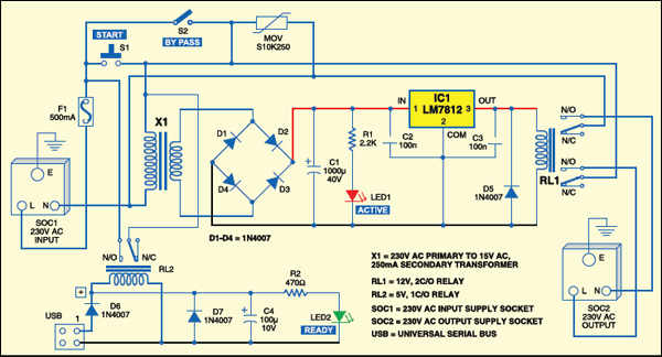
The power supply for the circuit is derived from the AC mains via transformer X1. The 15V AC available at the secondary winding of transformer X1 is first rectified by a bridge rectifier comprising diodes D1 through D4, smoothed by capacitors C1 and C2, and regulated by IC LM7812 (IC1). The regulated 12V DC is used to energise relay RL1. LED1 works as a power ‘active’ indicator.

Circuit operation
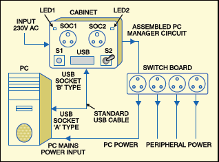
To set up the circuit, first, connect the input socket (SOC1) of the circuit to a proper AC mains wall outlet using a three-core power cable. Now connect one end of a standard USB cable to the B-type USB input socket and the other end of the cable to any vacant USB port (A-type) of the PC. Finally, plug one standard four-way switchboard (extension cord) into the supply output socket (SOC2) of the circuit and take power from this switchboard to activate all loads like the monitor, scanner, printer and even your PC.
To activate the PC manager circuit, proceed as follows: Press ‘start’ switch S1 and hold it in this position for a few minutes. When power-active indicator LED1 lights up, relay RL1 energises and the 230V mains power supply from SOC1 is fed to output socket SOC2 through the contacts of relay RL1.Now start your computer as usual, by pressing the power button on the front panel. When the PC runs, there will be 5V DC at the USB interface socket. As a result, relay RL2 energises via diode D6. The contacts of relay RL2 close switch S1 permanently, and LED2 glows continuously.
Release ‘start’ switch S1. Now your PC manager is ready to use.When you switch off your PC, relay RL2 de-energises. As a result, electric power from the switchboard (to which all peripherals are connected) is cut off. Switch S2 works here as an emergency bypass switch.
Construction & testing
Assemble the circuit on a general-purpose PCB and enclose in a suitable cabinet. Connect SOC1, SOC2 and USB socket along with switches S1 and S2 and LEDs (LED1 and LED2) on the front panel of the cabinet. Refer Fig. 2 for connections.
EFY note
Take care during fabrication and testing, as the circuit is at mains potential and may give you a lethal shock.
The project was first published in June 2009 and has recently been updated.
