


 Primarily intended for installation into a desktop PC, this versatile PC timer with adjustable time output provides controlled ‘on’ time for PC peripherals like printers, scanners and desktop reading lamps. As it is designed for an input voltage of 12 volts, it may also be useful in your lab.
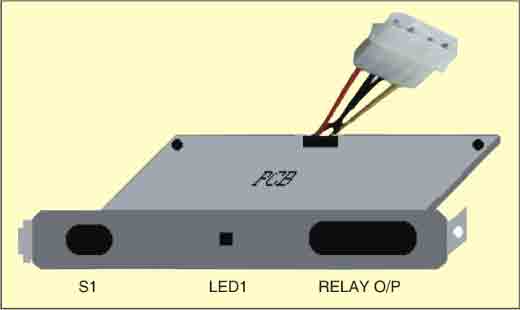
If you intend to use the circuit mainly as a portable timer, it is best installed in its own case. Alternatively, if the circuit is to be used as a PC’s internal timer, build it into the PC’s case (system box). It is easy to secure the circuit board against one of the metal pull-out panels at the rear of the PC. What is left to be done is drilling of holes in the metal bracket for the switch (S1), indicator LED1 and relay output connectors.
PC timer circuit
To connect the input voltage, hook up the circuit’s input supply points to the PC’s internal power supply cabling. Any unused 4-way drive live power connector (+5V/0V/0V/+12V) of the ATX SMPS can be used for powering the circuit.

As shown in Fig. 1, the fixed three-terminal voltage regulator IC 7809 (IC1) provides 9V from the PC’s SMPS to the circuit. Diode D1 protects against accidental polarity reversal. LED1 is a power on/off indicator.
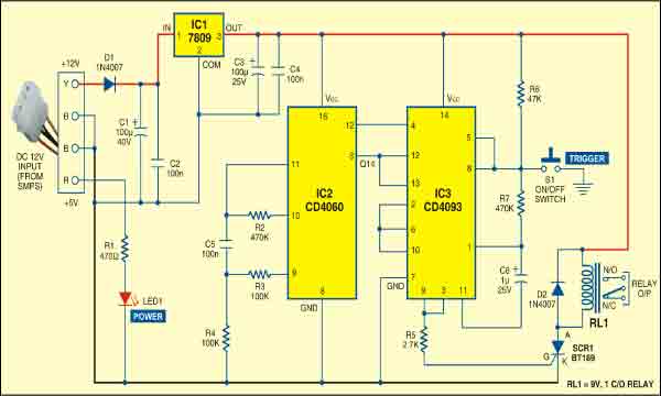
The circuit is built around a 14-stage ripple-carry binary counter CD4060 (IC2) and a quad 2-input NAND Schmitt CD4093 (IC3).The timer-controlled relay energises after the period determined by R-C time constant components R2 and C5. With component values as shown (R2=470 kilo-ohms and C5=100 nF), the relay energises after 10 minutes and latches. The time-out period may be altered by changing the value of R2 and/or C5. You can use a preset, in series with R2 and pin 10 of IC2, to set the time.
To start the timer, simply press switch S1 momentarily. IC2 starts oscillating and after six seconds, the output of IC3 at pins 3 and 9 provides gate voltage to trigger SCR1. As a result, the relay energises and latches to activate the connected load. The relay remains latched until switch S1 is pressed again.
Construction & testing
Assemble the circuit on a general purpose PCB and enclose in a suitable cabinet as shown in Fig. 2. Provide a suitable connector on the PCB for connecting the power supply from the SMPS of your PC.
The article was first published in 2010 and has recently been updated.
