


 Here is a PIN diode based fire sensor that activates an alarm when it detects fire. Thermistor based fire alarms have a drawback; the alarm turns on only if the fire heats the thermistor in close vicinity. In this circuit, a sensitive PIN diode is used as a fire sensor for a longer-range fire detection.

 It detects visible light and infrared (IR) in the range of 430nm – 1100nm. So visible light and IR from the fire can easily activate the sensor to trigger the alarm. It also detects sparks in the mains wiring and, if these persist, it gives a warning alarm.
It is an ideal protective device for showrooms, lockers, record rooms and so on. Author’s prototype is shown in Fig. 1.

PIN diode based fire sensor
PIN diode BPW34 (Fig. 2) is used in the circuit as light and IR sensor. BPW34 is a 2-pin photodiode with anode (A) and cathode (K). The anode end can easily be identified from the top-view flat surface of the photodiode. A small solder point to which a thin wire is connected is the anode and the other one is the cathode terminal.
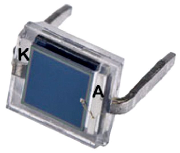
BPW34 is a tiny PIN photodiode or mini solar cell with radiant sensitive surface that generates 350mV DC open-circuit voltage when exposed to 900nm light. It is sensitive to natural sunlight and also to light from fire. So it is ideal for use as a light sensor.
BPW34 photodiode can be used in zero-bias as well as reverse-bias states. Its resistance decreases when light falls on it.

Circuit diagram
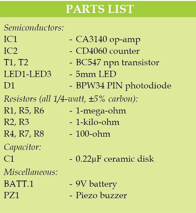
Circuit diagram of the PIN diode based fire sensor is shown in Fig. 3. It is built around 9V battery, PIN diode BPW34 (D1), op-amp CA3140 (IC1), counter CD4060 (IC2), transistors BC547 (T1 and T2), a piezo buzzer (PZ1) and a few other components.
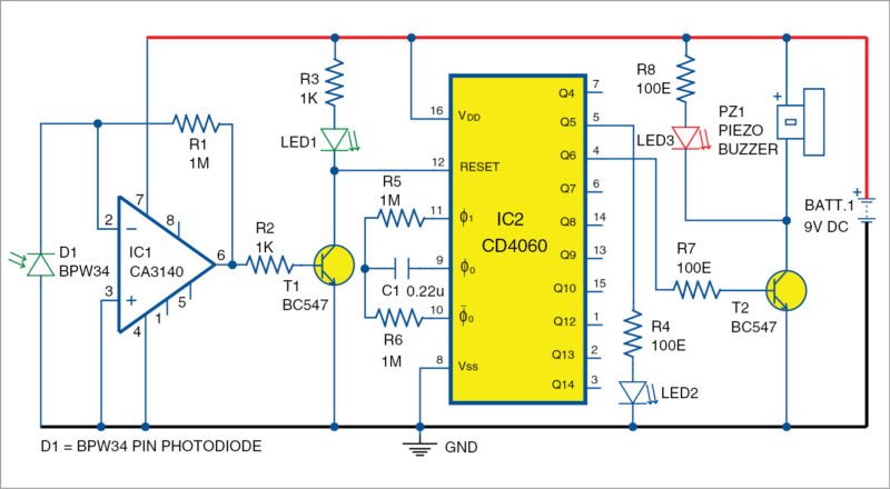
In the circuit, PIN photodiode BPW34 is connected to the inverting and non-inverting inputs of op-amp IC1 in reverse-biased mode to feed photo current into the input of op-amp. CA3140 is a 4.5MHz BiMOs op-amp with MOSFET inputs and bipolar output.
Gate-protected MOSFET (PMOS) transistors in the input circuit provide very high input impedance, typically around 1.5T ohms. The IC requires very low input current, as low as 10pA, to change output status to high or low.
In the circuit, IC1 is used as a transimpedance amplifier to act as a current-to-voltage converter. IC1 amplifies and converts the photo current generated in the PIN diode to the corresponding voltage in its output. The non-inverting input is connected to the ground and anode of photodiode, while the inverting input gets photo current from the PIN diode.
Circuit operation
Large-value feedback resistor R1 sets the gain of the transimpedance amplifier since it is in inverting configuration. Connection of non-inverting input to ground provides low impedance load for the photodiode, which keeps the photodiode voltage low.
The photodiode operates in the photovoltaic mode with no external bias. Feedback of the op-amp keeps the photodiode current equal to the feedback current through R1. So the input offset voltage due to the photodiode is very low in this self-biased photovoltaic mode. This permits a large gain without any large-output offset voltage. This configuration is selected to get large gain in low-light conditions.
Normally, in ambient light condition, photocurrent from the PIN diode is very low; it keeps output of IC1 low. When the PIN diode detects visible light or IR from fire, its photo current increases and transimpedance amplifier IC1 converts this current to corresponding output voltage. High output from IC1 activates transistor T1 and LED1 glows. This indicates that the circuit has detected fire. When T1 conducts, it takes reset pin 12 of IC2 to ground potential and CD4060 starts oscillating.
IC2 is a binary counter with ten outputs that turn high one by one when it oscillates due to C1 and R6. Oscillation of IC2 is indicated by the blinking of LED2. When output Q6 (pin 4) of IC2 turns high after 15 seconds, T2 conducts and activates piezo buzzer PZ1, and LED3 also glows. The alarm repeats again after 15 seconds if fire persists.
You can also turn on an AC alarm that produces a loud sound by replacing PZ1 with a relay circuitry (not shown here). The AC alarm is activated through contacts of the relay used for this purpose.
Construction and testing
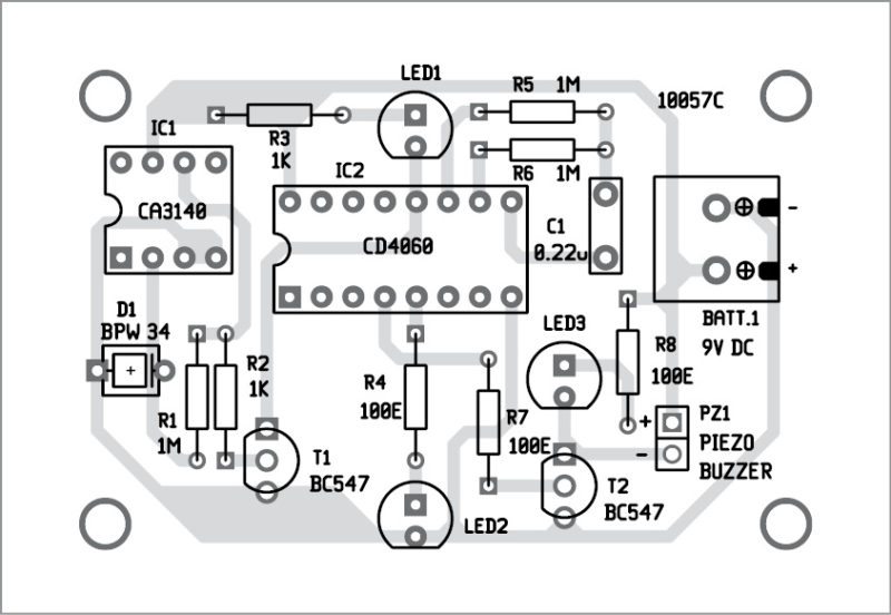
A single side PCB for the PIN diode based fire sensor is shown in Fig. 4 and its component layout in Fig. 5. Enclose the PCB in a small box in such a way that you can connect PIN diode BPW34 easily at the rear side of the box. Install the PIN diode in a suitable place and cover it such that normal light/sunlight does not fall on it.

Testing the circuit is simple. Normally, when there is no fire flame near the PIN diode, the piezo buzzer does not sound. When a fire flame is sensed by the PIN diode, piezo buzzer sounds an alarm. Its detection range is around two metres. It can also detect sparks in the mains wiring due to short-circuit.
Download PCB and component layout PDFs: click here
You may also like: click here
The article was originally published in June 2016 and has been recently updated.

How to give flame to pin diode and how the pin diode actually react . Please reply can you give video demo
Which software did you use for carrying out the simulation
No simulation software used here. We have directly tested it on PCB
LED 3 gets glow and buzzer gets activated after connecting the battery .Kindly suggest where the circuit gets mistake
Comment: PIN Photodiode BPW 34 can available easily in the market
Yes, it is easily available. You can buy it from various online stores including element14.com. The link is:
http://in.element14.com/vishay/bpw34/photodiode/dp/327426?mckv=sVFrvT9vR|pcrid|86555411440&CMP=KNC-GIN-GEN-SKU-VIS
Comment:please reply immediately sir am selecting this project it’s very argent
The sensor you mentioned above is being activated even though it is not exposed to flame
Please suggest something to rectify this issue.
the sensor is a photo diode,so it senses light.i.e: it does not senses the flame ,it senses the light from the flame ,so it easily gets activated when it is exposed to light.So the above model is used in lockers such that if any one tries to open it or when it catches fire the sensor gets activated.
what makes this project different fromthe fire sensors on maarket now
How to modify the circuit for ordinary photodiode???
how much cost needed to build this project???
You can build the circuit within Rs 500
Pls, I want to do this project. Can I get someone who can do it fr me and I learn through d person. If yes how much and how can we meet.
Sorry, we are not providing such services
I can do it for u just hit me up……+254799559653 those are my personal contacts
sir, how to put on flame so test the circuit???
Comment: The sensor you mentioned above is being activated even though it is not exposed to flame
Please suggest something to rectify this issue.
NO DO IT YOURSELF
Can you send me the problem statement and justification of this project because am on working on it… Thanks….!!!
My Circuit also Detect Normal Light and activate the buzzer.
How to fix it??
Can i know it is work in morning??
Kindly elaborate your query.
Please reply immediately
Even for match stick fire also the alarm will be given then how can we rectify this
Could we use a series combination of cylindrical capacitor , valued 0.4763 microfarad each in place of ceramic disc capacitor , valued 0.22 microfarad . For the above mentioned fire alarm project based on PIN photo diode.
LED3 is glowing and buzzer also continuously beeping
Check if transistor T2 is faulty or connected in the wrong position
Sir @efylab, Can I extend the range it detects?
Which other component can replace the IC2 counter for simulation???
sir,
what is the response time/rise time of 1st half of circuit(just the detection by photodiode and led glowing?)
Hello, I would also like to know the response time of the circuit in detecting the fire and how the mentioned response time could be improved
I am a professor of electrical engineering. I would like to get complete knowledge about fire detector for
our university. I would like to get it installed as project.
Kindly supply all information regarding that on my mail.
pls i want to try this project in my house. can i get the full project.
Hi, the article contains the full project.
why the alarm repeats again after 15 seconds , why 15??
The project is designed to give alarm for 15 seconds if there is fire. Timing is decided by the resistors R5, R6 and capacitor C1. you can change these values inorder to change the output timing. Please refer the article for detail.
what is the hazards of this system?