


 Here is a high power incandescent electric portable lamp flasher. It is basically a dual flasher (alternating blinker) that can handle two separate 230V AC loads (bulbs L1 and L2).
The circuit is fully transistorised and battery powered. The free running oscillator circuit is realised using two low power, low noise transistors T1 and T2. One of the two transistors is always conducting, while the other is blocking. Due to regular charging and discharging of capacitors C1 and C2, the two transistors alternate between conduction and non-conduction states.
Portable lamp flasher circuit
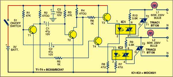
The collector of transistor T1 is connected to the base of driver transistor T4 through current limiting resistor R5. Similarly, the collector of transistor T2 is connected to the base of driver transistor T3 through limiting resistor R6. These transistors are used to trigger Triac1 and Triac2 (each BT136) through optotriacs IC1 and IC2, respectively, and switch on the power supply to external loads L1 and L2. IC1 and IC2 operate alternatively at a low frequency determined by the values of capacitors C1 and C2.

The oscillator circuit built around transistors T1 and T2 generates low frequencies. When transistor T3 conducts, IC1 is enabled to fire Triac1 and bulb L1 glows. Similarly, when transistor T4 conducts, IC2 is enabled to fire Triac2 and bulb L2 glows.
Connect the power supply line (L) of mains to bulbs L1 and L2, and neutral (N) to T1 terminals of Triac1 and Triac2. You can also connect neutral (N) line of the external 230V mains supply to both loads (bulbs L1 and L2) as a common line and then route supply line (L) to respective loads (bulbs L1 and L2).
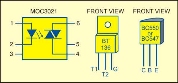
The circuit works off only 3 volts. Since current consumption is fairly low, two AA-type cells are sufficient to power the circuit. Assemble the circuit on a general-purpose PCB and enclose in a suitable plastic cabinet with integrated AA-size pen light cell holder. Drill holes for mounting the ‘on’/’off’ switch and power switching terminals. Also connect two bulb holders for bulbs L1 and L2. Refer Fig. 2 for pin configurations.
EFY note
While assembling, testing or repairing, take care to avoid the lethal electric shock.
The article was first published in June 2008 and has recently been updated.
