This circuit gives audio-visual indication of the failure and resumption of mains power. The circuit is built around dual timer IC LM556. When mains is present the bicolour LED glows in green colour, and when mains fails it turns red.
The AC mains is stepped down by transformer X1 to deliver the secondary output of 12V at 250 mA. The transformer output is rectified by a full-wave bridge rectifier comprising diodes D1 through D4, filtered by capacitor C1 and regulated by IC 7809 (IC1) to give regulated 9V DC to operate the circuit.
9V battery and pnp transistor T1 have been used here as the power source for red light indication of the absence of power. Transistor T1 can be made to conduct or cut-off easily by varying preset VR1.

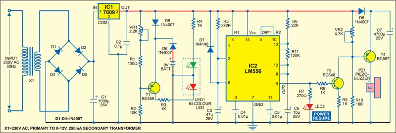
Initially, when mains is present, pnp transistor T1 is in cut-off state and therefore bicolour LED1 glows in green colour.
When power fails, pnp transistor T1 starts conducting and bicolour LED1 glows in red colour. Due to non-availability of Vcc voltage at pin 14 of IC2, its output pin 9 remains low and transistor T3 does not conduct. However, capacitor C7 (4700µF) holds adequate charge and hence transistor T4 conducts and piezobuzzer PZ1 sounds continuously for around eleven seconds until capacitor C7 discharges completely.

When power resumes, bicolour LED1 glows in green colour and the buzzer beeps for around 14 seconds.
Dual timer IC LM556 (IC2) sections have been used here in monostable and astable modes, respectively.
In the monostable section, location of the external timing capacitor determines whether a positive or negative output pulse is generated. Diode D7 ensures that even a momentary power loss will cause a pulse to be generated when the power resumes. With capacitor C3 connected to ground, a positive output pulse is generated according to the following relationship:
T = 1.1×R5×C3.
This positive output is present at pin 5 of IC2. Since IC2 is a dual-timer IC, its first output is directly fed to reset pin 10 of second section. Therefore the second timer of IC2 starts oscillating. Its frequency of oscillations (F0) is determined by resistors R6 and R11 and capacitor C6 as follows:
F0=1.4/(R6+2R11)×C6.
IC LM556 outputs frequencies in the form of pulses at its pin 9. These pulses are coupled to npn transistor T3, which conducts and cuts off depending on the output at pin 9 of IC2. Red LED2 is connected to pin 9 via current-limiting resistor R7 (270-ohm) to indicate power resumption.
The collector output of transistor T3 is directly fed to the base of pnp transistor T4, due to which base biasing of T4 varies and the buzzer beeps for around 14 seconds.