


 In many circuits, the switching action is performed by a relay, which in turn activates an external load. The power consumed by the relay may be unsuitable for battery-powered applications. Here is a simple solution using some inexpensive components to considerably save power.
Circuit and working of Relay Driver
Fig. 1 shows circuit diagram of the power-saving relay driver where resistor R1 and transistor T1 form a standard relay driver circuit.
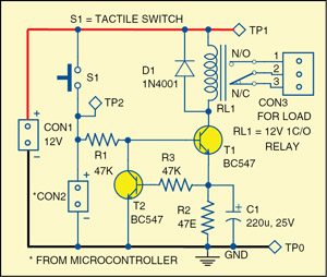
Once the relay is energised, its pole is pulled in to make contact with the N/O side, and it holds in that position with typically 75 per cent of its nominal-rated voltage. Power consumed by a relay coil during this holding time equals V²/R, where R is the resistance of the relay coil and V is the voltage. Here resistors R2 and R3, transistor T2 and capacitor C1 lower the power consumption after actuation by applying less than the normal operating power.

 Initially, when power is applied, capacitor C1 momentarily shorts resistor R2 and allows the full voltage across the relay to pull the pole contact, and then slowly the current through the capacitor drops.
 In the meantime, resistor R2 takes care of the current, ensuring it is just sufficient to hold the relay. The constant current mechanism formed by transistor T2 and resistors R2 and R3 effectively drive the relay at very less power.
Following calculations will help us understand how additional circuitry around relay driver transistor T1 saves power. The relay used here is a 12V, 400-ohm sugar-cube type. You can calculate the power saved as shown below:
Nominal current required for the relay (I)= 12V/400 ohm = 30mA
Power consumed by the relay=I2R=0.03A×0.03A×400 ohm =360mW
After the introduction of the circuit:
The current through the coil (I) =VBE/R2=0.6V/47 ohm=12mA
Power consumed by the overall circuit = V×I = 12×0.012=144mW
Power saved=360mW-144mW=216mW
So, we conclude that considerable power can be saved using the additional circuitry.
This makes it fairly simple for anyone to re-design a relay driver to reduce its power consumption without the use of any expensive components.
Construction and testing
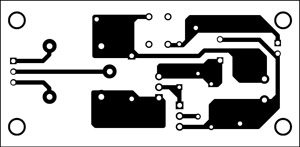
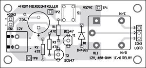
An actual-size, single-side PCB for the power-saving relay driver is shown in Fig. 2 and its component layout in Fig. 3.
Switch S1 is used to test the relay driver circuit. You can connect the output of a control circuit, such as a microcontroller, to CON2 for controlling the relay circuit.
CON3 helps in connecting to the electrical load. You can connect the load between N/O and pole contacts or N/C and pole contacts.
Download PCB and component layout PDFs: click here
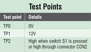
Before connecting the load to CON3, verify the test point voltages given in the table. You may reduce the value of R1 as per your requirement.
great job keep posting….
Is the microcontroller circuit is mandatory or we can remain the con2 open?
It depends on the application. When you want to control the load with microntroller to save the power, then it is essential to connect ouptput of microcntroller to CON2.
Actually Switch S1 is used to test the relay driver circuit and activate and de-activate the load connected to the contacts of the relay.
Without the connection of a microcontroller, will the relay work as a power-saving relay?
Yes. Microcontroller and switch are used to drive the relay only so it will save power in both cases.
Resistor R2 takes care of the current, ensuring it is just sufficient to hold the relay. The constant current mechanism formed by transistor T2 and resistors R2 and R3 effectively drive the relay at very less power.