


 This article presents a simple, universal low-cost power supply hub with quad-USB and variable voltage outputs, plus a battery charger. There are electronic equipment like battery chargers, electronic lamps and MP3 players that take power from USB ports, but there may not be sufficient ports or sufficient power available from the USB ports on a computer. In the simplest case, we use linear voltage regulators and not switched regulators.
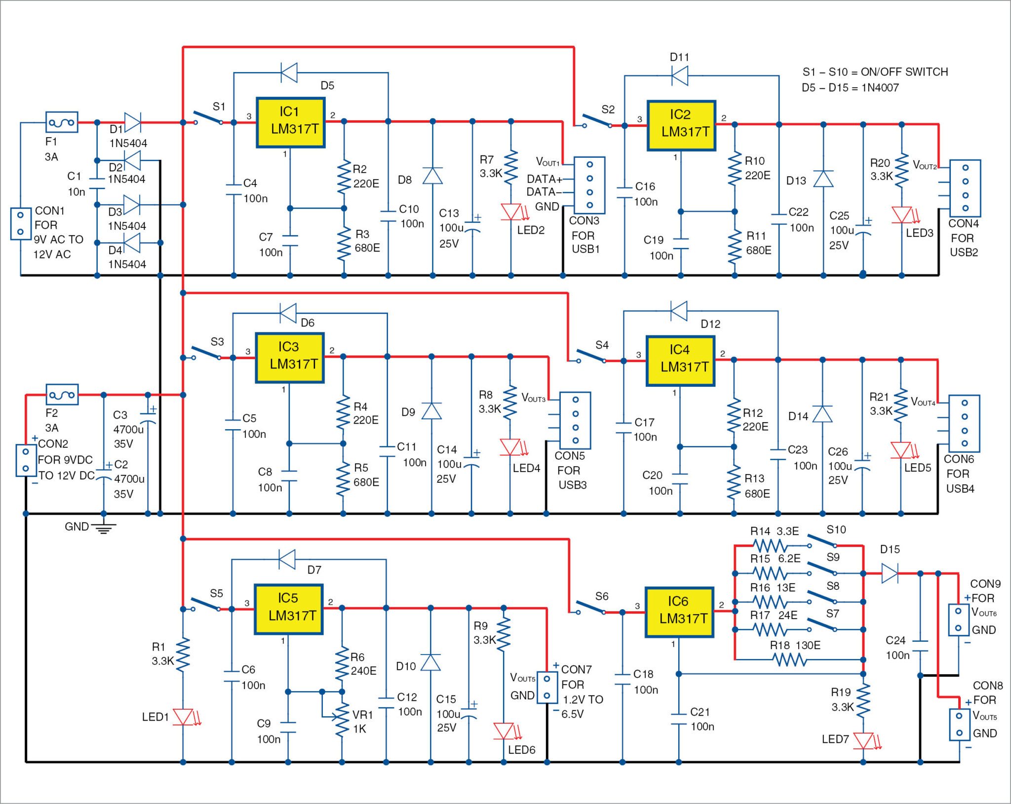
Fig. 1 shows one possible implementation of a power supply hub with the following main characteristics:
- 9V to 12V AC/DC input
- Four 5.1V outputs with USB connectors
- One variable output from 1.2V to 6.5V
- A constant-current output with a minimum of 10mA and a maximum of 400mA
- Individual on/off switches (S1 through S6) or jumpers for each output; all outputs controlled by adjustable linear voltage regulators LM317T in TO-220 package
Circuit and working
LM317T is a low-cost, adjustable voltage regulator. It can dissipate up to 20W as heat and produce up to 1.5A of current (refer the datasheet). Six LM317T regulators are used in this project to build a useful power supply hub that provides power supply for four USB devices (USB1 through USB4) at connectors CON3 through CON6.
In addition, one variable output (1.25V to 6.5V) is available at CON7 and a current generator output at CON8 for charging and maintaining the rechargeable batteries. Connector CON9 in parallel with CON8 is provided as an extra but optional outlet.
Voltages across the battery charger available at CON8 and adjustable output from IC5 available at CON7 should be measured with a voltmeter. Outputs at the USB connectors (CON3 through CON6) have LEDs for visual indications. Glowing of the LEDs indicates the presence of the power supply at each USB connector.
Switches
The circuit has ten switches, S1 through S10. S1 through S5 are used for switching on/off IC1 through IC5 and corresponding VOUT1 through VOUT5, respectively.
S6 is the on/off switch for IC6 and for output currents for charging and maintaining rechargeable batteries at CON8 and CON9. S7 through S10 determine the output current produced by IC6.
Voltage and current calculation. Voltage (VOUT1) produced from IC1 can be calculated with the formula:
VOUT1=1.25V×(1+R3/R2)=1.25V×4.09=5.11V
Similarly, you can calculate voltages VOUT2, VOUT3 and VOUT4.
These four voltages should be in the range of 5.1V to 5.2V or near the maximum of 5.25V for the USB standard voltage.
Maximum voltage produced by IC5 can be calculated using the relationship:
VOUT(max)=1.25V×(1+VR1/R6)=1.25V×(1+1000-ohm/240-ohm)=6.46V
For VOUT(min) you have around 1.25V from the datasheet of LM317T.
Minimum output current produced by IC6 is calculated using the relationship:
IOUT(min)=1.25V/R18=1.25V/130-ohm=9.6mA
Maximum output current produced by IC6 is calculated using the relationship:
IOUT(max)=1.25V/R14=1.25V/3.3-ohm=379mA
Table I gives the current produced by IC6 if you close only one of the switches between S7, S8, S9 and S10.

Heat-sink
IC1 through IC6 are mounted on individual heat-sinks with thermal resistance below 10°C/W.
Alternatively, IC1 through IC6 can be mounted on a common heat-sink with thermal resistance below 2°C/W, under the condition that these are properly isolated from the common heat-sink.
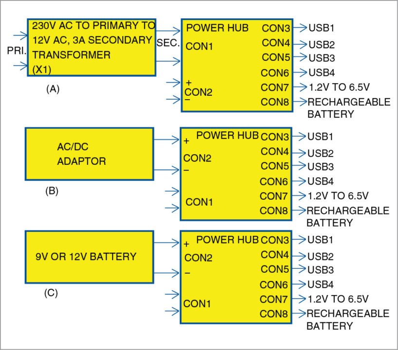
Input voltages
These are applied to CON1 or CON2. Fig. 2 shows the following three possible cases for input voltages to the power hub:
1. AC/AC transformer to CON1. CON 2 is not used.
2. AC/DC wall adaptor to CON2. CON 1 is not used.
3. 9V or 12V battery, including car battery, to CON2. CON 1 is not used.
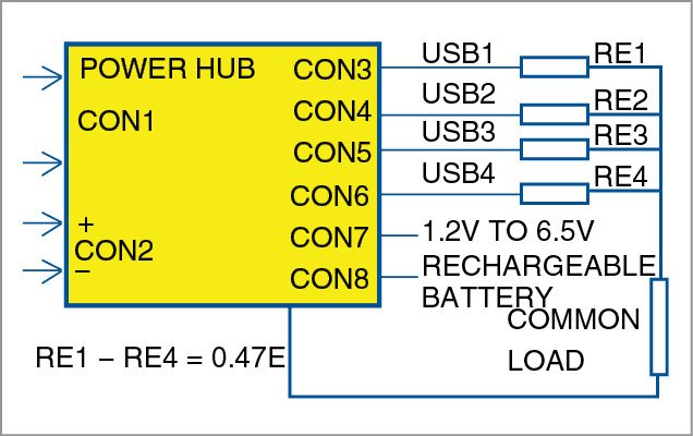
You may connect two to four USB outputs in parallel, as shown in Fig. 3. The condition is to use appropriate equalisation resistors (RE1 through RE4). In most cases, 0.47-ohm resistors are used.
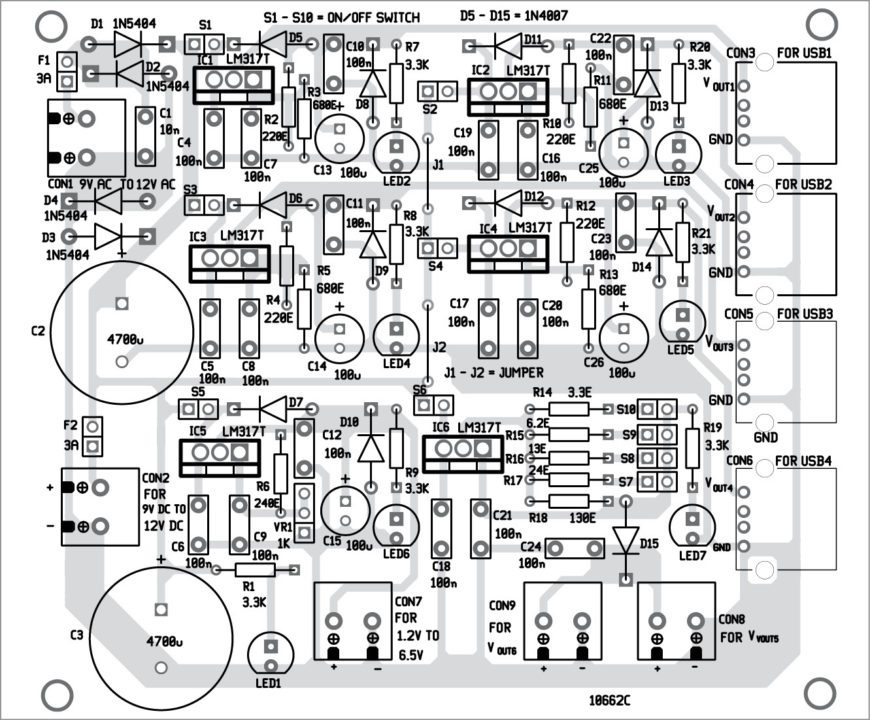
Construction and testing
An actual-size, single-side PCB for the power supply hub is shown in Fig. 4 and its component layout in Fig. 5. After assembling the circuit on the PCB, enclose it in a suitable box.
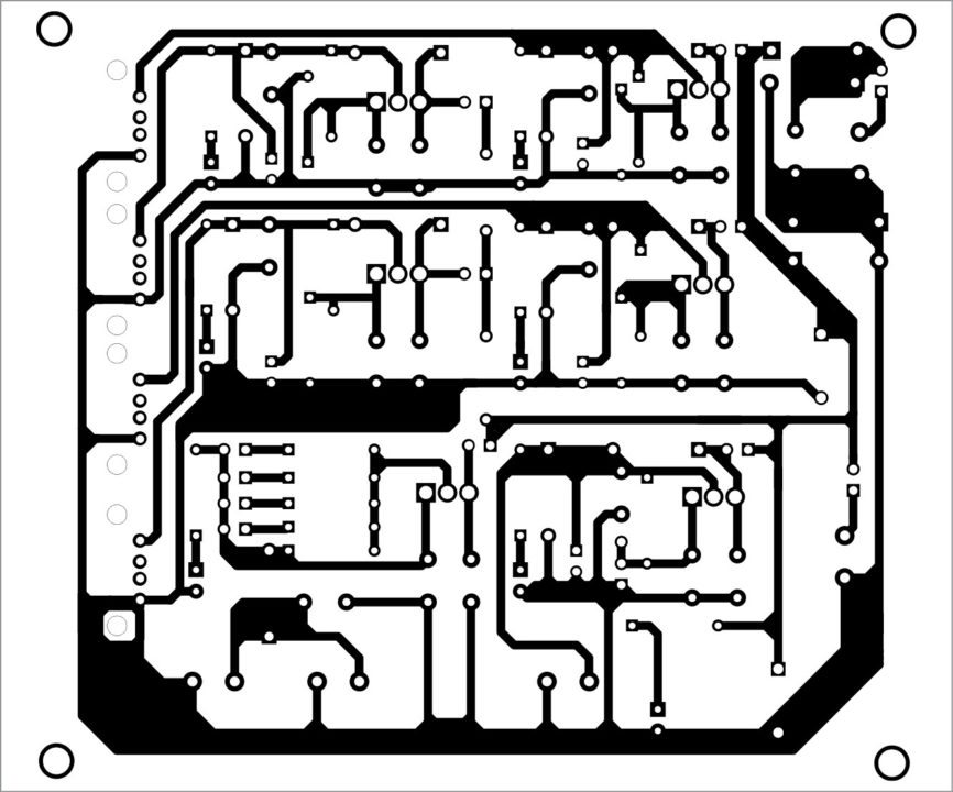
Download PCB and component layout PDFs: click here
The circuit can be connected to a 230V AC primary to 9V/12V, 3A secondary transformer X1 (not shown in Fig. 1). Secondary terminals of X1 should be connected across CON1. You can also use any 9V-12V AC/DC, 3A power adaptor or 9V-12V DC battery.
Petre Tzv Petrov was a researcher and assistant professor in Technical University of Sofia (Bulgaria) and expert-lecturer in OFPPT(Casablance), Kingdom of Morocco. Now he is working as an electronics engineer in the private sector in Bulgaria.
