


 This radio-cum-audio frequency signal generator can also be used as a beat frequency oscillator (BFO) for continuous-wave and single-sideband signals.
Fig. 1 shows the circuit of the audio frequency oscillator built around unijunction transistor 2N2646 (T1).
The advantage of using a unijunction transistor is that the audio frequency can be varied over a wide range by using preset VR1. You can fix the desired audio frequency by adjusting preset VR1. The audio frequency output obtained via capacitor C2 can be used to test audio equipment such as amplifiers. Using preset VR1, the audio frequency output can be varied from 50 Hz to 7.5 kHz.

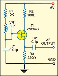
Fig. 2 shows the circuit of the radio frequency generator. The high-frequency oscillator is built around transistors T2 and T3. Signals from the collector of transistor T2 are fed to the base of transistor T3 via capacitor C4. The emitter junctions of both the transistors (T2 and T3) are grounded via resistor R5.
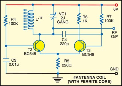
The frequency of oscillation depends on the resonant frequency of the L-C circuit connected to the collector of T2. The L-C circuit is built around coil L1 and 2J gang capacitor VC1. Any L-C circuit of suitable Q can be used with the circuit.
By varying 2J gang condenser VC1,the frequency of oscillation at the collector of transistor T2 can be varied from about 350 kHz to 1 MHz. The coil in the L-C circuit can be replaced with a MW oscillator coil or short-wave oscillator/antenna coil and the frequency of the oscillator varied from a few hundred kHz to a few MHz. By connecting the base of transistor T2 to the output of AF generator through a 100k resistor in series with C2, you can use the AF generator to modulate the RF signal.
In order to use the circuit as a BFO, set 2J gang capacitor such that the frequency of the oscillator is equal to the intermediate frequency of the receiver (which is usually 455 kHz). Alternatively, an intermediate frequency transformer (IFT) can be used as L-C circuit at the collector of T2. When the frequency of the oscillator is equal to the IF, a whistling sound is heard at all the stations on the receiver regardless of the frequency to which the receiver is tuned.
Assemble both the circuits on separate general-purpose PCBs and house in small boxes providing two terminals for 6V DC power supply and another two terminals for outputs.
