


 Manual buzzers used for quiz competitions in schools and colleges create a lot of confusion in identifying the first respondent. Although there are circuits using PCs and discrete ICs, they are either too expensive or limited to only a few number of players. The quiz buzzer circuit given here can be used for up to eight players, which is maximum in any quiz competition. The circuit uses IC 74LS373 and a few passive components that are readily available in the market.
The circuit can be divided into two sections: power supply and quiz buzzer. Fig. 1 shows the power supply section. The regulated 5V power supply for the quiz buzzer section is derived from AC mains. The 230V AC mains is stepped down to 7.5V AC by transformer X1, rectified by bridge rectifier BR1, filtered by C1 and regulated by regulator IC1. Capacitor C2 bypasses ripples in the regulator output.
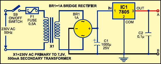
Fig. 2 shows the quiz buzzer section. At the heart of this section is IC 74LS373, an octal latch that is used to transfer the logic state at data input pins D0 through D7 to the corresponding Q0 through Q7 outputs. Data pins D0 through D7 are normally pulled low by resistors R1 through R8, respectively.

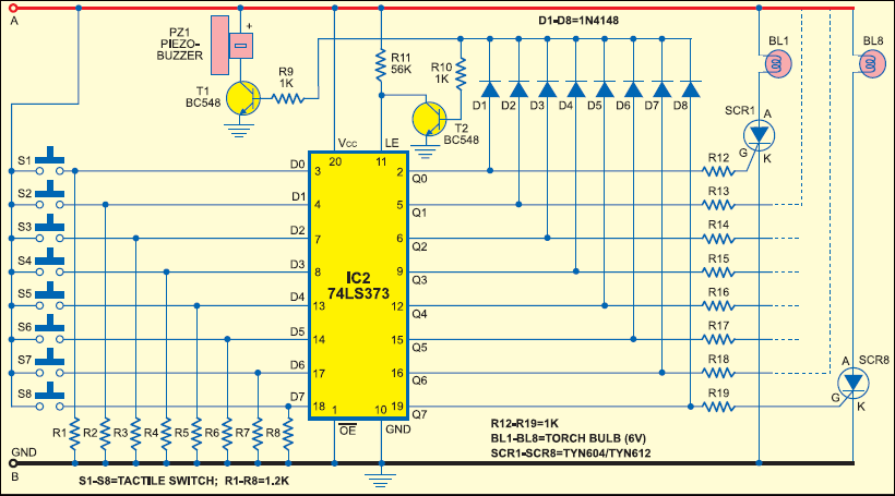
One terminal of push-to-on switches S1 through S8 is connected to +5V, while the other terminal is connected to the respective data input pins. The switches are to be extended to the players through cord wire. The torch bulbs BL1 through BL8 can be housed in boxes with the front side of the boxes covered with a white paper having the name or number of the contestant written over it for easy identification. Place the boxes above the head level so that these can be seen by the audience also.
When the power is switched on using switch S9 (provided terminals ‘A’ and ‘B’ of both the power supply and quiz buzzer sections are interconnected), the circuit is ready to use. Now all the switches (S1 through S8) are open and Q0 through Q7 outputs of IC 74LS373 are low. As a result, the gates of silicon-controlled rectifiers SCR1 through SCR8 are also low.
As soon as a contestant momentarily presses his respective switch, the corresponding output data pin goes high. This triggers the corresponding SCR and the respective bulb glows. At the same time, the piezobuzzer (PZ1) sounds as transistor T1 conducts.
Simultaneously, the base of transistor T2 becomes high to make it conduct. Latch-enable (LE) pin 11 of IC2 is tied to ground to latch all the Q0 through Q7 outputs. This restricts further change in the output state due to any change in the state of switches S1 through S8 by any other contestant. Only one of the eight torch bulbs glows until the circuit is reset by on/off switch S9.
More interesting projects available here.

I want this system to purchase
How can
Dear sir what is included in the kit. Can I use for playing Antakshari. Can I connect participants seating at the distance of the 10 feet. Kindly reply. thanks
What I am going to get in this, means will it be fully assembled or i have to make the connections
Please reply,
what is the rating of scr in this project
What all are the items I will get with the project?Does it will work with 10 m wire extension??
This is good & optimum circuit for school quiz event.
The SCRs can be replaced by simply LEDs if bulb is not required.
This is a very clear rendition of this circuit. Its inexpensive and functions well. Thank you for the quality schematic.
You are most welcome.
I’ve made 8 team quiz buzzer control using IC 7475 which was published in EFY in Feb 2008 issue so far I can remember.