


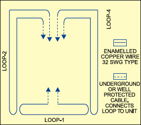
 You can use this simple and reliable digital security system as a watch dog by installing the sensing loops around your building. You have to stretch the loop wires two feet above the ground to sense the unauthorised entry into your premises.
Digital Security System Circuit
Wire loops 1, 2 and 4 are connected to the A, B and C inputs of 7-segment decoder 4511 (IC1), respectively, while the D input of IC1 is grounded permanently. The loops are also connected to a dual 3-input NOR gate and inverter CD4000 (IC2) to activate the alarm.
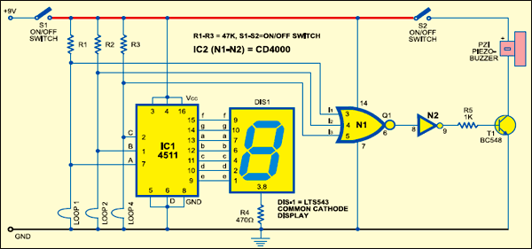
Fig. 1 shows the circuit of the digital security system, while Fig. 2 shows the proposed wiring diagram for the loops around the premises. Before using this security system, make sure that loops shown in Fig. 2 are connected as shown in Fig. 1. If you don’t want to use a buzzer, switch it off by opening switch S2.

The circuit works off a 9V regulated power supply. However, battery back-up is recommended. A common-cathode, 7-segment display (LTS543) is used for displaying whether the loops are intact or not.
If loop 1 is broken, the display will show ‘1’. If two or all the three loops are broken, the display will show the sum of the respective broken loop nently. The loops are also connected to a dual 3-input NOR gate and inverter CD4000 (IC2) to activate the alarm.
Fig. 1 shows the circuit of the digital security system, while Fig. 2 shows the proposed wiring diagram for the loops around the premises. Before using this security system, make sure that loops shown in Fig. 2 are connected as shown in Fig. 1. If you don’t want to use a buzzer, switch it off by opening switch S2.
The circuit works off a 9V regulated power supply. However, battery back-up is recommended. A common-cathode, 7-segment display (LTS543) is used for displaying whether the loops are intact or not.
Circuit operation
If loop 1 is broken, the display will show ‘1’. If two or all the three loops are broken, the display will show the sum of the respective broken loop numbers. For example, if loops 1 and 4 are broken, the display will show 5(1+4).
When all the three loops are intact, the display will show ‘0.’ All the three inputs of gate N1 remain low to give a high output. This high output is further given to gate N2 and, as a result, its output remains low. This keeps transistor T1 in cut-off position and the piezobuzzer does not sound.
When any loop is broken, the output of NOR gate N1 goes low, while the output of gate N2 goes high. Transistor T1 conducts and the buzzer sounds to alert you. You can mute the buzzer by switching off power to the circuit through switch S1.
The circuit was first published in March 2005 and has recently been updated.
