


 This simple key-operated gate locking system allows only those persons who know the preset code to open the gate. The code is to be entered from the keypad within the preset time to operate the motor fitted in the gate. If anyone trying to open the gate presses a wrong key in the keypad, the system is disabled and, at the same time, sounds an alarm to alert you of unauthorised entry.
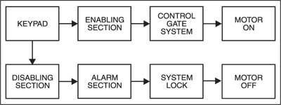
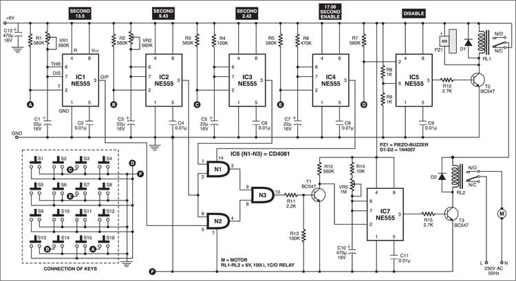
Figs 1 and 2 show the block and circuit diagrams of the key-operated code locking system, respectively. Connect points A, B, C, D, E, F and ground of the circuit to the respective points of the keypad. Keys S7, S16, S14 and S3 are used here for code entry, and the remaining keys are used for disabling the system. It is very important to press the keys in that order to form the code. To start the motor of the gate, press switches S7, S16, S14 and S3 sequentially. If the keys are pressed in a different order from the preset order, the system will lock automatically and the motor will not start.
Initially, 6V is not available at pin 14 of AND gate IC6, so no pulse reaches the base of npn transistor T1 to trigger timer IC5 and, as a result, the gate doesn’t open. To enable the system, first you have to trigger IC4. Pressing switch S7 triggers timer IC4 to provide 6V to IC6 for approximately 17 seconds. Within this time, you have to press switches S16, S14 and S3 sequentially. As a result, the outputs of timers IC1, IC2 and IC3 sequentially go high. These high outputs are further given to gates N1 and N2 of IC6 to trigger IC7 via npn transistor T1. The time durations for the high outputs of IC1, IC2 and IC3 are preset at 13.5, 9.43 and 2.42 seconds, respectively.

When all the four switches (S7, S16, S14 and S3) are pressed sequentially, timer IC7 triggers to start the motor for the preset period to open the gate. Once the time elapses, the motor stops automatically. The ‘on’ time for the motor can be selected by adjusting preset VR5. Here, the minimum ‘on’ time is 5.17 seconds and the maximum ‘on’ time is 517 seconds.
If a switch other than S7, S16, S14 and S3 is pressed, IC5 triggers to energise relay RL1, which disconnects the power supply of the second relay and the system gets locked and piezo buzzer PZ1 sounds an alarm to alert you that somebody is trying to open the gate lock.
Now to stop the sound and reset the system again press any key (other than S7, S16, S14 and S3) from the keypad.
The circuit works off 6V DC regulated power supply and can be easily assembled on a general-purpose PCB.

Please give me components list for simple key operated gate locking system. And which type of motor used in this project.