


 Morse code contests are still held in some parts of the world. Practising the Morse code with a simple Morse key kit is interesting.
The circuit given here can be used to generate audible tones using input switches. If you have a Morse code table, you can use the circuit as a Morse code contest trainer. It can be used for self-practice but it is better to practise with two persons because that is closer to the real conditions. In the simplest case, the manual telegraph key is a mechanical key that interrupts the signal from a squarewave generator. The circuit given here is based on that principle.
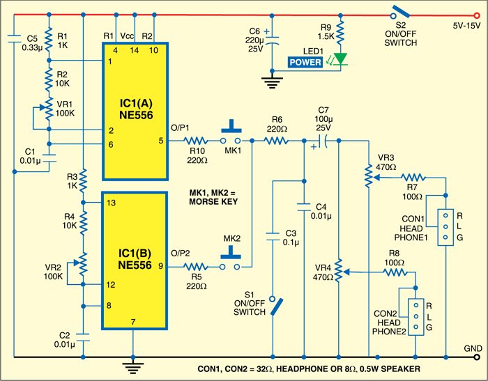
The circuit consists of a popular NE556 dual timer IC. It has two inbuilt timers IC1(A) and IC1(B) configured to generate square waves. The oscillation frequencies of both the generators are individually adjustable from 600 Hz up to 6 kHz using presets VR1 and VR2. Here oscillation frequency of the generators is set to around 1 kHz. However, in a real application, both the generators may run on different frequencies.

The signal from IC1(A) is con-trolled with Morse key MK1, while the signal from IC1(B) is controlled with Morse key MK2. The outputs of both generators are combined through capacitor C7 so that both users can hear the Morse signal simultaneously.
To produce a pleasant Morse key tone, the output signals are filtered with capacitors C4 and C3. If switch S1 is open, only C4 is active. If switch S1 is closed, both the capacitors are used.
The device can drive two 32-40-ohm headphones or two 8-16-ohm small loudspeakers connected to its connectors CON1 and CON2. The signal amplitudes on CON1 and CON2 can be adjusted using presets VR3 and VR4, respectively.
The advantage of using the headphones is that others in the house or in the radio club are not disturbed by the exercise.
The time period (T1) of the square wave from the first generator is calculated as:
T1 =0.693[R1+ 2(R2+VR1)] C1
The time period (T2) of the square wave from the second generator is calculated as:
T2 = 0.693[R3+ 2(R4+VR2)] C2
If the frequencies are fixed, potentiometers VR1 and VR2 can be removed.
The circuit is powered by a 5V-15V DC supply. It can also work off a single 4.5V 3R12 battery.