


 This simple radio frequency (RF) based code lock incorporates a pair of 433MHz ready made RF transmitter and receiver modules. It is a remote-controlled and code-protected locking system. The code is fixed, hence it is easy to implement and requires very less power.
Circuit and working of RF Code Lock
The circuit has a transmitter and a receiver. The transmitter circuit shown in Fig. 1 is built around 433MHz RF transmitter module (TX1), encoder HT12E (IC1) and a few other components.
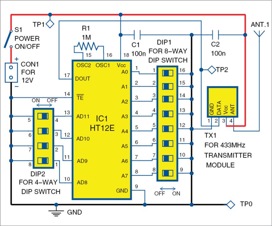
Signal transmission starts as soon as you switch on the circuit using switch S1. HT12E encoder IC1 generates eight address bits and four data bits, and employs amplitude shift keying (ASK) modulation. The code is programmed using address lines. Data pins AD8 to AD11 are connected to dual-in-line package switch DIP2 to set data for transmission.
Address bits A0 to A7 of IC1 are set to 11111111 via switch DIP1. Programmed address and data are combined and then transmitted together through 433MHz RF module (TX1). Address of the transmitter has to match with the address of the receiver to successfully receive data.

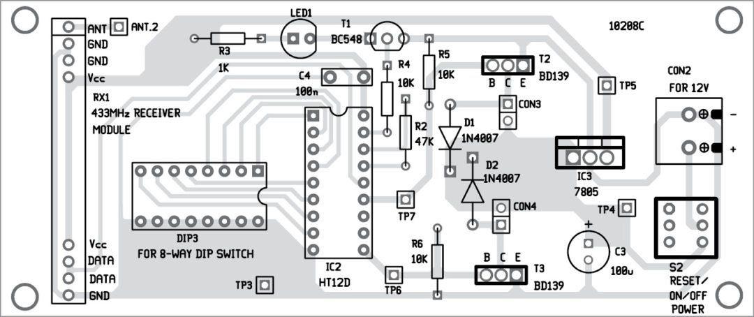
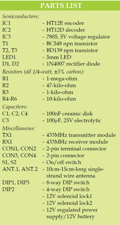
Receiver circuit shown in Fig. 2 consists of 433MHz RF module (RX1), decoder HT12D (IC2), 5V voltage regulator 7805 (IC3), transistors BC548 (T1) and BD139 (T2 and T3), two solenoid locks connected across connectors CON3 and CON4 and a few other components. Coded signal transmitted by the transmitter is processed by decoder IC2 at receiver side. Address bits A0 to A7 of IC2 are set to 11111111 using DIP switch DIP3.
If the received address bits match 11111111, transmitted data will be available across data pins (D8 through D11) of IC2. Here, 11111111 is the fixed code but can be changed by altering the address bits as per requirement.
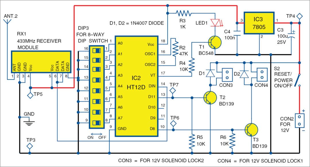
Flashing of LED1 indicates that a valid signal has been received at the receiver. It will not flash if there is a mismatch of the addresses of IC1 and IC2.
In this circuit we have used only data pins 10 (D8) and 13 (D11) of IC2, which drive the two solenoid locks connected across CON4 and CON3, respectively.
Make AD8 and AD11 of IC1 high in order to make D8 and D11 high, respectively. You can also connect two more locks at D9 and D10 of IC2 along with relay driver transistors.
Once solenoid is activated, output remains latched and lock remains open (because it is a fail-secure type lock). Reset the lock by switching S2 or S1 off and on again.
Construction and testing
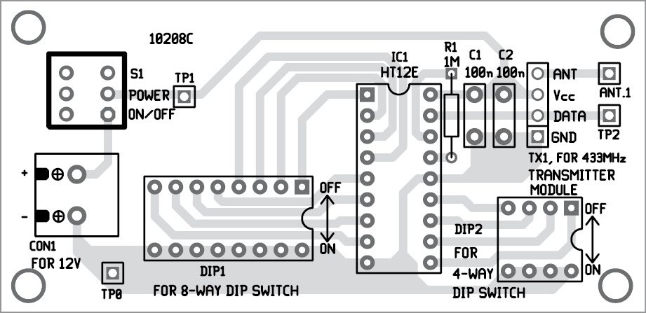
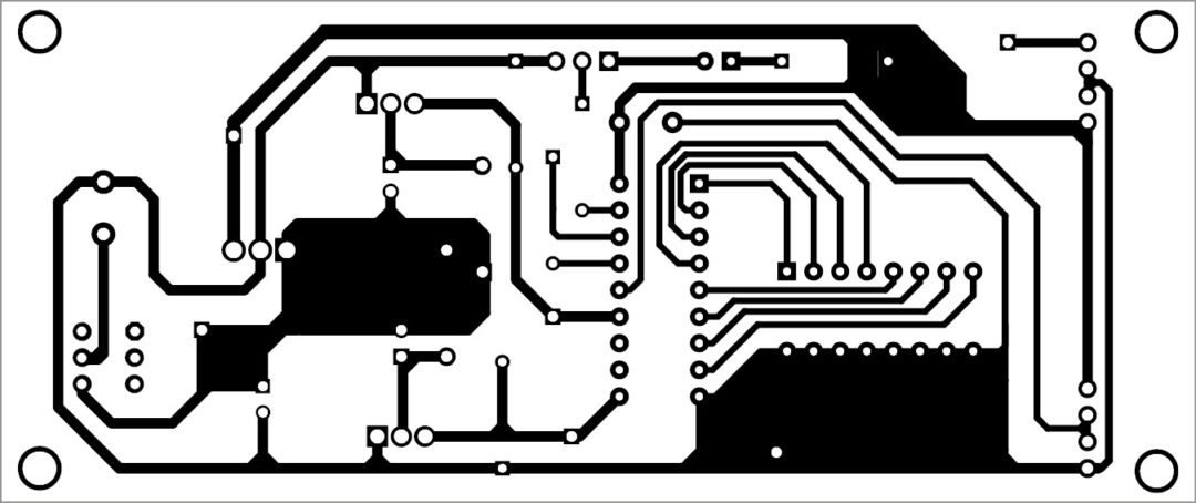
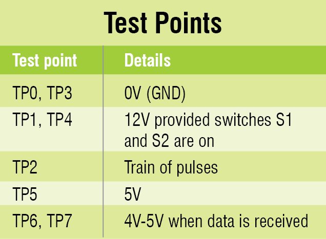
An actual-size, single-side PCB pattern of the transmitter circuit is shown in Fig. 3 and its component layout in Fig. 4. An actual-size, single-side PCB pattern of the receiver circuit is shown in Fig. 5 and its component layout in Fig. 6. Both circuits require 12V regulated power supply. After assembling the circuit on the PCBs, enclose these in two separate plastic boxes. Before using the circuit, verify voltages are as per the test points given in the table.

Download PCB and component layout PDFs: click here
Suppose you want to open solenoid lock1 connected across CON4. For this, set data bits AD8 to AD11 to 1000 using DIP2. Push all three pins 11, 12 and 13 (except pin 10) of IC1 to ground. Now, to open the lock, power on the receiver circuit using S2; D8 through D11 should go low.
Next, switch on the transmitter circuit. In the receiver, D8 of IC2 will go high and transistor T3 will conduct, which, in turn, will open solenoid lock1 at CON4. You can remotely operate the solenoid lock from a distance of 30 metres or more depending on the RF modules used.
You may also like: click here
Shashwat Mishra is pursuing BE from BIT Mesra. His interests include designing electronics circuits
