


 Low-pass filters are widely used in the audio domain. Their most important application is in communication receivers and communication audio circuitry. These filters, when used for audio communications, start attenuating frequencies above 3.4 kHz, as the bandwidth of the human voice (as far as voice clarity and intelligibility are concerned) is 300 Hz to 3.4 kHz.
Sixth Order Butterworth Low Pass Filter
Here we describe a sixth order Butterworth Low Pass filter circuit that exhibits a flat passband and attenuation rate of 120 dB per decade after 3.4 kHz. This means that a signal with a frequency of 34 kHz is attenuated by 120 dB compared to a signal of 3.4 kHz. No ripples are seen in the passband and stopband. A filter with flat passband and ripple-free attenuation band is known as a ‘Butterworth’ filter.
Although the Butterworth circuitry is supposed to exhibit a gain of 1 (or 0 dB), a small gain is seen in the circuit. Nevertheless, the shape of the transfer curve (frequency domain) is unaffected, and this minor gain is in no way detrimental to the performance of the circuit.

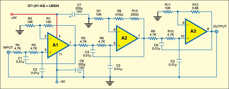
The most striking feature of this circuit is dual voltage supply of ±3V. This has been done to ease circuit design by reducing the number of components. The power supply is built around a battery pack comprising four AA-size cells. These four cells are placed in series, with the positive terminal of the first cell fed to +3V line, the negative terminal of the last cell fed to –3V line, and the connection between the second and third cells serving as 0V or ground line. Capacitors C7 and C8 (each 220µF) between +3V and 0V, and 0V and –3V, improve the AC performance of the circuit, by AC shorting the rails to ground potential.
Circuit operation
The LM324, a popular quad op-amp IC, is used here. It introduces minimal noise and houses all the four op-amps in a single 14 dual-in-line package, thereby allowing for circuit compactness. Of the four op-amps, only three are used here.
The three op-amps (A1 through A3) have similar circuits wired around them, differing only in the value of feedback resistors (R1, R8+R13, R12). The feedback resistors help in setting the gain of each stage, which is necessary to realise the Butterworth filter. Resistors R3 through R6, R9 and R10 in conjunction with capacitors C1 through C6 determine the low-pass cut-off frequency of the filter. (f=1/(2πRC)=1/(2π×0.01µF×4.7kΩ)=3.386 kHz.
Construction & testing
Assemble the circuit on a general-purpose PCB and enclose in a small box. You can bring out the input and output terminals on the front panel of box for ease of giving input and taking the output signal.
Do you like this circuit? You may also like these DIY circuits.
The project was first published in May 2009 and has recently been updated.