


 An emergency light can come in handy at all sorts of time, especially when there’s a power outage. Now you need not fear dark nights when power breaks down. Here’s a white LED-based smart emergency light that automatically turns on when mains power supply fails.
Emergency light working
The circuit consists of power supply, battery charger and switching sections. The power supply and charger sections are built around transformer X1, diodes D1 and D2, transistor T1, resistors R1 and R2, and zener diode ZD1. The power supply for the circuit is derived from AC mains by using 9V-0-9V, 250mA step-down transformer X1. Diodes D1 and D2 rectify the AC voltage into DC voltage, which is smoothed by filter capacitor C1. The unregulated DC voltage is regulated by transistor T1 along with resistor R1 and zener diode ZD1. The regulated DC voltage, via resistor R2, charges the lead-acid battery. Diode D3 connects the battery power supply to the switching circuit when mains power is unavailable.
Circuit diagram
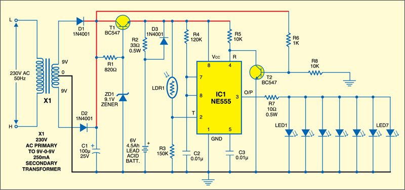
The switching circuit is built around an NE555 timer (IC1), which is wired in monostable mode. When a low voltage is applied at trigger pin 2 of IC1, the timer activates and its output pin 3 goes high. It remains in that state until IC1 is triggered again at its pin 2.

Light-dependant resistor LDR1 is connected between the positive supply of the battery and trigger pin 2 of IC1. Resistor R3 is connected between pin 2 of IC1 and ground. The resistance value of LDR1 remains high in dark (at night) and low in ambient light (in daytime). This phenomenon is utilised to control the switching circuit.
Circuit operation
Working of the circuit is simple. In daytime, when ambient light falls on LDR1, its resistance decreases to make trigger pin 2 of IC1 high. As a result, output pin 3 goes low and the LEDs (LED1 through LED7) remain off.
At night (in the dark), the resistance of LDR1 increases and a low voltage is applied to trigger pin 2 of IC1. This activates the monostable and its output goes high to make all the LEDs glow.
When mains power is available, reset pin 4 of IC1 is grounded via transistor T2 and its output pin 3 remains low. As a result, the LEDs don’t glow. When mains power fails, transistor T2 does not conduct and reset pin 4 of IC1 gets positive supply through resistor R5. As a result, the output of IC1 goes high to light up the LEDs. Due to pulsating DC output at pin 3 of IC1, it can drive seven LEDs (LED1 through LED7).
Assemble the circuit on a general-purpose PCB and enclose in a cabinet with enough space for the battery. Mount the seven white LEDs on the front panel of the box. Fix LDR1 away from the white LEDs to prevent their light from falling on LDR1.
More interesting projects available here.
Can you please send what all components are required for Smart emergency light and cost of each components
Does battery stop charging when it becomes full in this circuit?
I want report sir
Hi Ragavan, full information is already shared within the article.
sir can you please provide any making video for this smart emergency light project
We do not have the video for this project
Leaving many things aside, Why to connect emitter of T1 to NE555 if you want to keep the LEDs off while mains voltage is present… Or if sometimes you may need to switch ON the LEDs then there should be some provision like a switch in series with R6 to break the resetting of IC…