


 The emergency light is an automatic system in which a rechargeable battery-operated light source turns on as soon as the mains power fails. When the mains supply resumes, the lamp turns off. Usually, 6V sealed maintenance-free (SMF) batteries are used in portable emergency lights. Many low-cost lights give no indication when the battery goes flat, so there is the risk of battery failure. Here is a battery guard circuit for emergency lights having no deep-discharge protection circuitry. It disconnects the bulb in case the battery voltage goes below a safe value (5V).
Block diagram
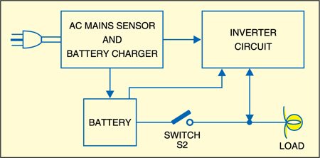
Shown above is the block diagram of an emergency light. It essentially consists of a source of electricity, a rechargeable battery pack, an automatic sensing circuit to check the presence (or absence) of mains supply and a charger circuit. The sensing circuit connects the lamp (or a compact fluorescent tube inverter) to the battery in the event of mains failure and disconnects it when the mains supply resumes. When AC mains supply is available, the charger circuit charges the battery.
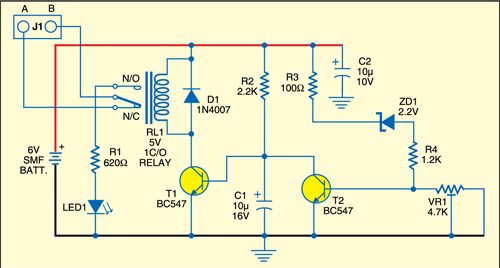
Battery guard circuit
The battery guard circuit is shown below. It uses two transistors, one Zener diode and a few passive components. LED1 indicates the battery voltage status. The glowing of LED1 indicates that the battery voltage is less than the safe voltage and the bulb is disconnected from the battery.

Circuit operation
When the battery is fully charged, the battery voltage reaches the base of transistor T2 through R3, ZD1 and R4. Transistor T2 starts conducting making transistor T1 to cut-off. The relay remains de-energised and the lamp is connected to battery jumper J1 used for connecting points A and B.
When the battery voltage goes below the safe level, transistor T2 is cut-off. As a result, T1 conducts and the relay energises to disconnect the load from the battery.

Using preset VR1, set the conduction voltage for transistor T2 such that it conducts 5V or higher voltage. For any value below 5V, transistor T2 stops conducting, driving transistor T1 into conduction. As a result, the relay energises to disconnect the bulb from the battery and the battery stops deep-discharging.
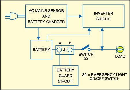
Construction & testing
Assemble the battery guard circuit on any general-purpose PCB and enclose in a box. Fit the unit (internally) to one side of the emergency light cabinet with the help of screws and spacers. Connect the normally closed contacts and pole of the relay shown in the circuit, in series with the on/off switch of the emergency light as shown in the wiring diagram.
The article was first published in July 2009 and has recently been updated.
