


 The world cannot continue to rely for long on fossil fuels for its energy requirements. Fossil fuel reserves are limited. In addition, when burnt, these add to global warming, air pollution and acid rain. A solar lighting system goes a long way.
Solar photovoltaic systems are ideal for providing independent electrical power and lighting in isolated rural areas that are far away from the power grid. These systems are non-polluting, don’t deplete the natural resources and are cheap in the long run. The aim of this circuit is to demonstrate how we can utilise solar light to electrify the remote areas, i.e., how we can store the solar energy and then use it for small-scale lighting applications.
Solar cells generate direct current, so make sure that DPDT switch S1 is towards the solar panel side. The DC voltage from the solar panel is used to charge the battery and control the relay.

Solar Lighting System Circuit
Capacitor C1 connected in parallel with a 12V relay coil remains charged in daytime until the relay is activated. C1 is used to increase the response time of the relay, so switching occurs moments after the voltage across it falls below 12V. Capacitor C1 also filters the rectified output if the battery is charged through AC power. The higher the value of the capacitor, the more the delay in switching. The switching time is to be properly adjusted because the charging would practically stop in the early evening while we want the light to be ‘on’ during late evening.
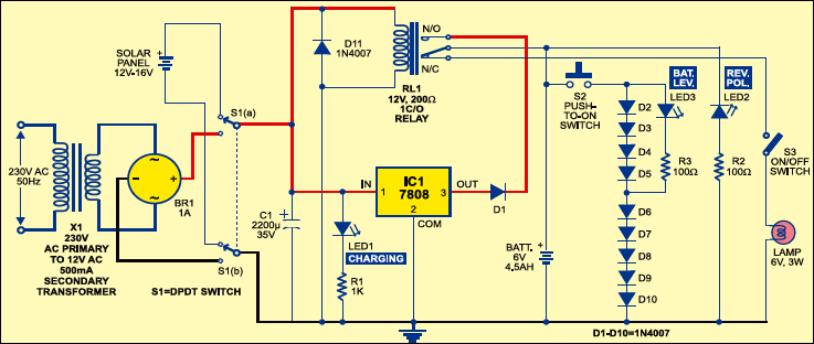
During daytime, relay RL1 energises, provided DPDT switch S1 is towards the solar panel side. Due to energisation of relay RL1, the positive terminal of the battery is connected to the output of regulator IC 7808 (a 3-terminal, 1A, 8V regulator) via diode D1 and normally-open (N/O) contacts of relay RL1. Here we have used a 6V, 4.5Ah maintenance-free, lead-acid rechargeable battery. It requires a constant voltage of approx. 7.3 volts for its proper charging.
Even though the output of the solar panel keeps varying with the light intensity, IC 7808 (IC1) is used to give a constant output of 8V. Diode D1 causes a drop of 0.7V, so we get approx. 7.3V to charge the battery. LED1 indicates that the circuit is working and the battery is in the charging mode.
Nighttime operation
At night, there will be no generation of electricity. The relay will not energise and charging will not take place. The solar energy stored in the battery can then be used to light up the lamp. A 3W lamp glows continuously for around 6 hours if the battery is fully charged. Instead of a 3W lamp, you can also use a parallel array of serially connected white LEDs and limiting resistors to provide sufficient light for even longer duration.
In case the battery is connected in reverse polarity while charging, IC 7808 will get damaged. The circuit indicates this damage by lighting up LED2, which is connected in reverse with resistor R2. However, the circuit provides only the indication of reverse polarity and no measure to protect the IC. A diode can be connected in reverse to the common terminal of the IC but this would reduce the voltage available to the battery for charging by another 0.7 volt.
Estimating the voltage
There is also a provision for estimating the approximate voltage in the battery. This has been done by connecting ten 1N4007 diodes (D2 through D11) in forward bias with the battery. The output is taken by LED3 across diodes D2, D3, D4 and D5, which is equal to 2.8V when the battery is fully charged. LED3 lights up at 2.5 volts or above. Here it glows with the voltage drop across the four diodes, which indicates that the battery is charged. If the battery voltage falls due to prolonged operation, LED3 no longer glows as the drop across D2, D3, D4 and D5 is not enough to light it up. This indicates that the battery has gone weak. Micro-switch S1 has been provided to do this test whenever you want.
If the weather is cloudy for some consecutive days, the battery will not charge. So a transformer and full-wave rectifier have been added to charge the battery by using DPDT switch S1. This is particularly helpful in those areas where power supply is irregular; the battery can be charged whenever mains power is available.
This solar lighting system was first published in April 2006 and has recently been updated.

Can you show this connections on bread board????with each components description!!!
please send me parts list||||