


 This novel sound scanner sweeps all sound vibrations in its vicinity and converts them into audible beeps. It can sense sound vibrations up to a distance of 6 metres and can be used to monitor sit outs, car porches, and other places of your house. The sound scanner operates a beeper whenever the microphone detects a sound.
Sound scanner circuit
Sound vibrations are sensed by the input section comprising the condenser microphone and op-amp IC 741C (IC1). Resistor R1 determines the sensitivity of the microphone. Condenser microphone picks up sound vibrations and converts them into electrical signals, which are fed to the input (pin 2) of IC1 via coupling capacitor C1. Amplified signals from IC1 are taken to the non-inverting input pin 3 of IC2 (IC 741C) through C2. IC2 is configured as a comparator.
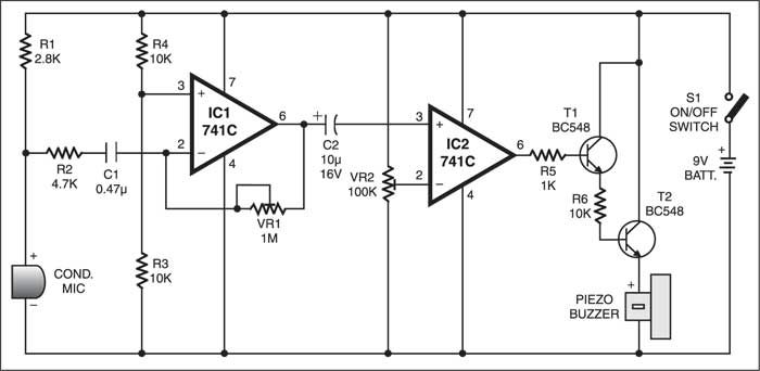
A reference voltage controlled by VR2 is applied to the inverting input pin 2 of IC2. The output of IC2 is used to trigger Darlington pair transistors T1 and T2. A piezobuzzer connected to the emitter of T2 produces audible beeps as the microphone senses sound.

The circuit can be easily assembled on a common PCB or Veroboard. Adjust VR1 to get the maximum gain of IC1. Adjust VR2 to get the maximum sensitivity of IC2.
Circuit operation
If a continuous beep is heard through the piezobuzzer, adjust the wiper of VR2 towards the ground line. Keep the piezobuzzer inside the room and the sensor in the place that is to be monitored. Connect the condenser microphone using a two-core shielded wire and enclose it in a small case to increase its sensitivity. Battery operation is recommended as the circuit may pick up noise from AC mains.
The article was first published in May 2003 and has recently been updated.

as i tried this but it is not working…
Kindly elaborate your query.