


 Electronic devices consume some power even in the standby mode, i.e., when they have been switched off using a remote handset but not the mains power switch. For instance, when a CRT TV or PC monitor is in use, it consumes 80-100 watts of power. In the standby mode too, it draws a few watts of power. Thus if you leave these devices in standby mode for a long time, they may inflate your electricity bill.
The circuit described here helps you save on your electricity bill by disconnecting the device (say, CRT TV) from the mains power automatically within a few seconds of switching-off of the TV using the remote. (But you may have to get up to switch the TV on again!) The principle of electromagnetic induction is used to activate the circuit.

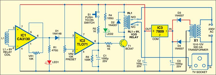
The circuit senses high-energy electromagnetic radiation from the CRT monitor when it is ‘on.’ A relay coil (L1) connected between inverting pin 2 and non-inverting pin 3 of IC CA3130 (IC1) senses the electromagnetic radiation from the monitor to generate a minute current. IC CA3130 is a CMOS op-amp with gate-protected p-channel MOSFETs in the inputs. It has very high input impedance and requires very low input current (typically, 5 pA). The high input impedance and low input current make IC1 suitable for this application. The internal bias of IC1 at 5 pA is sufficient for its working, so external biasing is not required. Preset VR1 is used for offset null adjustments so that the output of IC1 is low when the TV is in the standby mode.
Initially, when the TV is ‘off,’ output pin 6 of IC1 is low and LED1 doesn’t glow. To start the TV, press switch S1 for a few seconds. Capacitor C1 charges through resistor R2 and transistor T1 conducts to energise relay RL1. The relay gives power to the TV through its normally-open (N/O) contacts. When the TV is switched on, the sensor coil receives the electromagnetic radiation, the output of IC1 goes high and LED1 glows. The high output from IC1 is fed to the non-inverting input of IC TLO71 (IC2) via diode D1 and the TV remains ‘on.’ IC2 is a low-noise, JFET input op-amp.
When you switch off the TV using the remote control, the electromagnetic field around it disappears and the output of IC1 goes low. As a result, the output of IC2 also goes low and transistor T1 stops conducting. The time taken by capacitor C1 to discharge through resistor R3 gives delay of a few seconds to de-energise the relay after which the mains power to the TV is cut off. The TV can be switched on again only by momentarily pressing switch S1.
Power supply for the circuit is derived from a 12V-0-12V step-down transformer (X1). Diodes D3 and D4 rectify the secondary output of the transformer and capacitor C3 filters the ripples. IC 7809 (IC3) provides regulated 9V to the circuit for operation.
Assemble the circuit on a general-purpose PCB and enclose in a suitable cabinet with an AC socket for the TV. Place the unit near the TV (preferably on the top or sides) and supply the power. Adjust VR1 until LED1 goes off. At this time, the relay should remain de-energised. Press switch S1 for a few seconds until the relay energises to switch on the TV and LED1 glows. Now if you release switch S1, the TV will remain ‘on.’ Use the remote to switch it off in standby mode.
EFY warning. As the circuit uses 230V AC, take care to avoid electric shock.
