


Traditional Street lighting systems frequently suffer from problems such as false activation and a lack of precise control. This article provides a unique street light controller project that addresses these restrictions.
Street Light Controller Circuit
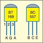
The circuit is built around popular op-amp IC 741 (IC1), 14-bit ripple counter CD4060 (IC2), SCR BT169, BC557 and other components. IC1, along with LDR1, enables IC2, which drives transistor T1 into conduction. IC2 is also used to trigger SCR1 to switch on the street light. Removal of trigger turns the light ‘off.’
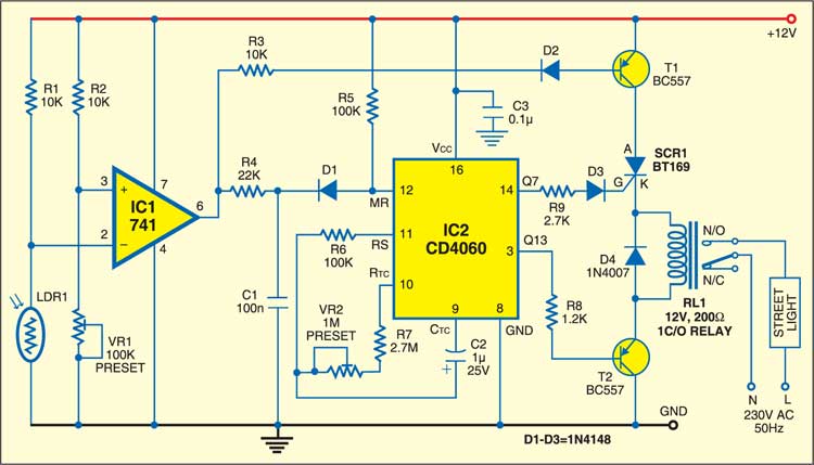
IC CD4060 has an inbuilt oscillator around its pins 9, 10 and 11. Pin 12 is the master reset (MR) control. The oscillator is disabled when pin 12 is high and enabled when pin 12 is low.

Circuit Operation
In daytime, i.e., when light is falling on LDR1, its resistance decreases and the high output at pin 6 of IC1 cuts off pnp transistor T1 and disables IC2. At this stage, SCR1 remains untriggered to switch off the street light.
At night, i.e., when no light is falling on LDR1, its resistance increases, and low output pin 6 of IC1 drives pnp transistor T1 into conduction. This enables IC2 and its internal oscillator starts oscillating.
After a preset time, pin 14 (Q7) of IC2 goes high and SCR BT169 is triggered through resistor R9 and diode D3. This energizes RL1, and the street light is turned on. This time interval can be varied by connecting the gate of SCR1 to pins 6, 13, etc of IC CD4060 (not shown in Fig. 1).
Transistor T2, which is normally conducting, is driven into non-conduction when output pin 3 (Q13) of IC2 goes high, which de-energizes relay RL1 to switch off the street light. This time can be adjusted with the varying preset resistor VR2.
Put simply, the street light turns ‘on’ when Q7 of IC2 goes high and ‘off’ when Q13 goes high, provided pin 12 of IC2 remains low.
Also Check: Reference Design For A Solar Powered Street Light
Construction and Testing
The circuit works off a regulated 12V DC. You can assemble it on any general-purpose PCB and enclose it in a suitable cabinet. The mains AC terminal for the street light is connected to the normally-open (N/O) contact of relay RL1, so the street light turns on when the relay energized.
Core Advantages
- Efficient Day-Night Control: Uses LDR1 to detect light changes and control streetlight activation with precise timing.
- Adjustable Timing: Allows adjustment of light-on and light-off intervals using VR2 and the ripple counter.
- Reliable Switching Mechanism: Incorporates SCR and relay control for consistent operation and reduced false triggering.
- Simple Assembly: The compact circuit is easy to build and requires only standard PCB assembly.
Related Projects
The article was published in March 2007 and updated in November 2024.
Pin 14 of ic 4060 is clock input how can you take output for scr gate from clock pin of ic
Pin14 is output, after preset time, pin 14 (Q7) of IC2 goes high.
I am not able to understand the working of
Ic CD4060
Dear Dharmendra,
The CD4060 IC has an in-built oscillator module. On every negative transition of clock pulse, the counter value gets incremented by 1 in binary numbers. If reset pin12 is grounded it enables. If pin12 is HIGH,ic will reset and oscillations starts from beginning.
Frequency is decided by formula f= 1/ ( 2.5 x R x C),where R and C are resistors and capacitor connected across pin9,10,11.
Regards
WHATS THE USE OF D1?
Dear Deepak,
In circuits where current should only flow in one direction, diodes are used to block reverse current.
Also diode is used for signal isolation, ensuring that signal flows in only one direction.
Regards