


 It is quite common to find extension phones in homes these days but this kind of convenience also comes with a distinct disadvantage: the possibility of another person listening in. This is where a telephone sentry comes in. This circuit, when attached to a telephone, is able to detect the presence of one or two additional telephones connected to the same line.
The telephone sentry uses a common 9V transistor battery and is easy to connect to the telephone line. Current drawn from the battery is 10 to 20 milliamperes, which permits a long battery life. Two LED lamps (LED2 and LED3) are used to warn you when additional telephone extensions are in use.
Under normal conditions, both LEDs will be ‘off.’ If one extension phone is picked up, one LED will light up. The second LED will light up if another extension phone is also picked up. The third LED (LED1) provides indication of the battery condition. As long as the battery has a sufficient terminal voltage to properly operate the unit, LED1 will illuminate.

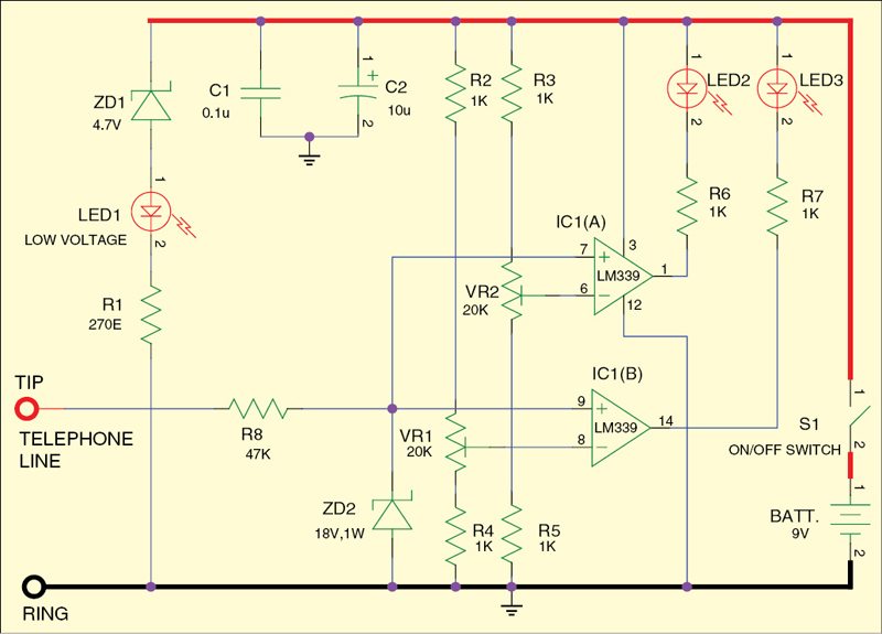
The key to the operation of the telephone sentry is the voltage which appears across the telephone line. The telephone line acts like a battery of about 48V DC behind a source impedance of about 1000 ohms. When one telephone is connected across the line, the DC voltage drops to about 4.6V. When a second telephone is added across the first, the voltage drops to about 3.2V. When a third telephone is connected, the voltage drops to about 2.3V. Although these levels will vary somewhat from one telephone system to another, the change in voltage as each telephone is added is sufficient for a voltage comparator circuit to detect.
The heart of the telephone sentry is a quad single-supply comparator IC LM339 (IC1). Only two sections of this chip are used. The reference voltage for each voltage comparator section is provided by adjusting potentiometers VR1 and VR2.
The voltage detection level has been set at 3.9V for section A of IC1, and 2.75V for section B. These voltages are fed to the inverting input of each voltage comparator—pins 6 and 8 of IC1. The non-inverting input of each voltage comparator section is connected to the output of the telephone line through a 47-kilo-ohm resistor (R8), which provides a high impedance to the telephone line.
If only one telephone is connected across the line, the voltage fed to the non-inverting inputs of the two comparator sections will be 4.6V, which is greater than 2.7V and 3.9V. This will cause the output of the comparators to be 5V. Thus neither of the LEDs will glow. Should one extension be picked up, the voltage across the line will be more than 2.75V but less than 3.9V. This will cause the output of IC1(A) to go to zero volts and LED2 glows. Similarly, if another extension is picked up at the same time, LED3 will also glow.
Assemble the circuit on a general-purpose PCB and enclose in a suitable cabinet. Connect one two-pin terminal connector to the telephone lines. Drill holes in the cabinet so that the LEDs may stick out.
The circuit presents a high impedance to the telephone line and will not affect the telephone’s performance.