


As most electronics components’ characteristics vary with temperature, they are selected as per expected operating temperature range of the equipment. So it is important that the equipment stays within the temperature range for which it is designed.
This circuit warns when the temperature reaches predefined danger levels. Here the predefined levels are set to 45°C, 65°C, 85°C and 105°C, but one can set any other temperature levels to suit the equipment in use.

Circuit and working
Fig. 1 shows the temperature monitoring circuit. It is built around 10k NTC thermistor NTC1, shunt regulator TL431 (IC1), popular comparator LM324 (IC2) and some other components.
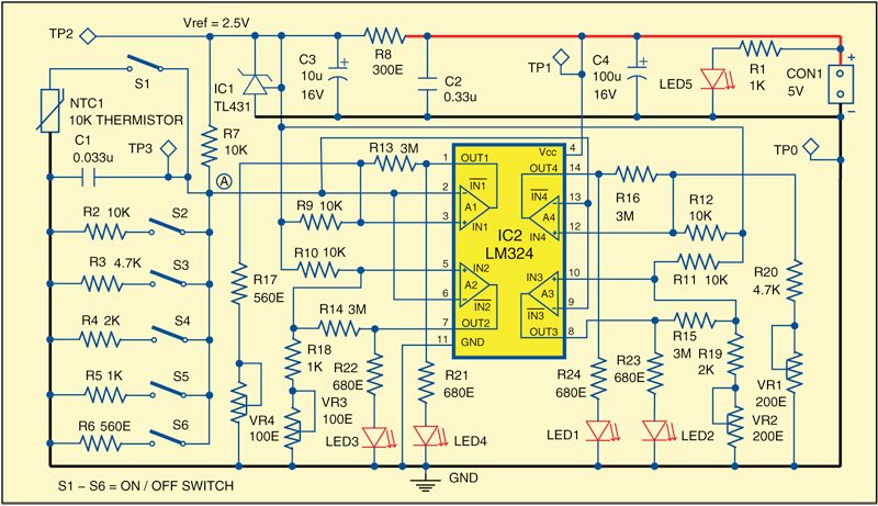
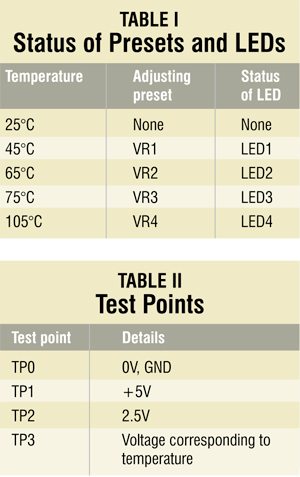
IC2 activates corresponding LEDs (LED1 through LED4) when the temperature of thermistor NTC1 reaches the predefined level (refer Table I). The temperature is sensed by NTC1 and the produced corresponding voltage at point ‘A’ is fed to inverting terminal of all the four op-amps (A1 through A4). Switch S1 should be closed for this operation. This voltage level is compared with the reference voltage at non-inverting terminals of each op-amp. The reference voltage is obtained by voltage dividers from 2.5V reference source, which is produced using shunt regulator IC1. The reference voltage for each comparator can be set using presets VR1 through VR4.
The switches S2 through S6, together with resistors R2 through R6, are used for calibration purpose. For example, op-amp A4 of IC2 compares the voltage levels at point A (changing with change in temperature) with the reference voltage at its pin 12. The voltage level at pin 12 of A4 is adjusted with preset VR1. Switches S2 through S6 are used to simulate voltage levels corresponding to different temperatures.
A4 is tuned for 45°C by keeping switch S3 in closed position and trimming preset VR1 until LED1 glows. S1 should be open during calibration. The same procedure is repeated for comparator A3, A2 and A1 to tune them for 65°C, 85°C and 105°C. Table I shows the presets and LEDs corresponding to each temperature level. After calibration, open switches S2 through S6.
Download PCB and component layout PDFs: click here
Construction and testing
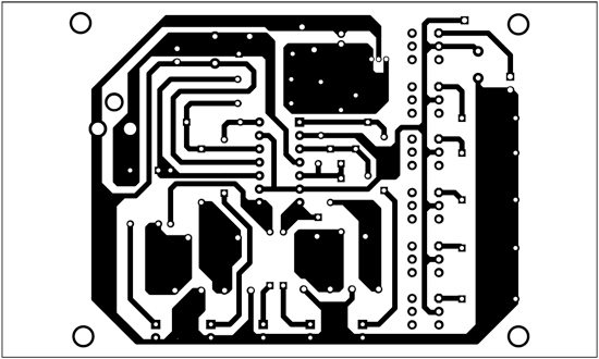
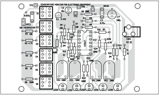
An actual-size, single-side PCB for the temperature monitor is shown in Fig. 2 and its component layout in Fig. 3. After assembling the circuit on a PCB, enclose it in a suitable box. Fix connector CON1 for the power supply.
To test the circuit for proper functioning, verify input power supply at TP1 with respect to TP0. Check 2.5V reference voltage at TP2. The voltage at TP3 will vary with the temperature.
The author was a researcher and assistant professor in Technical University of Sofia (Bulgaria) and a lecturer in the Kingdom of Morocco. Now he is working as an electronics engineer in the private sector in Bulgaria

Sir / Mam I am a diploma student. I need an above project block diagram and explanation. Help me sir.