


 This simple traffic controller can be used to teach children rudiments of traffic rules.
The circuit (shown in Fig. 1) uses readily available components. It mainly comprises rectifier diodes (1N4001), a 5V regulator 7805, two timers IC 555, two relays (5V, single-changeover), three 15W, 230V bulbs and some discrete components.
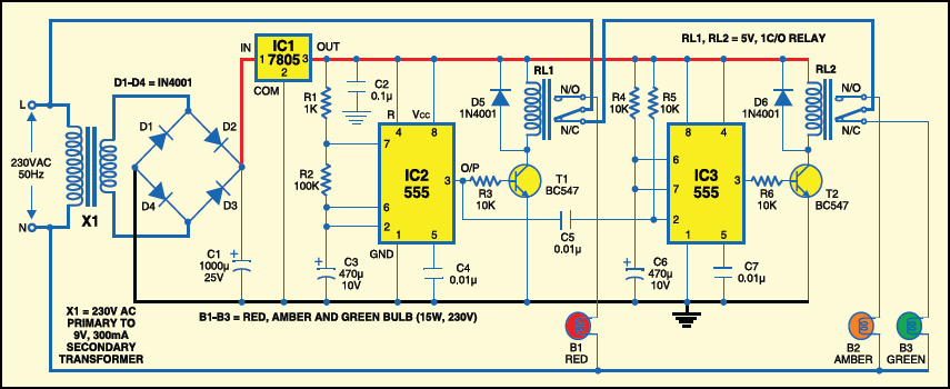
Mains power is stepped down by transformer X1 to deliver a secondary output of 9V, 300 mA. The transformer output is rectified by a full-wave bridge rectifier comprising diodes D1 through D4, filtered by capacitor C1 and regulated by IC 7805 (IC1).

IC2 is wired as a multivibrator with ‘on’ and ‘off’ periods of approximately 30 seconds each with the component values selected. As soon as mains power is switched on, pin 3 of IC2 goes high for 30 seconds. This, in turn, energises relay RL1 through transistor T1 and the red lamp (B1) glows through its normally-open (N/O) contact. At the same time, mains power is disconnected from the pole of relay RL2.
As the ‘on’ time of IC2 ends, a high-to-low pulse at its pin 3 triggers IC3 through C5. IC3 is configured as a monostable with ‘on’ time of about 4 seconds, which means pin 3 of IC3 will remain high for this period and energise relay RL2 through driver transistor T2. The amber lamp (B2) thus lights up for 4 seconds.

As soon as 4-second time period of timer IC3 at pin 3 lapses, relay RL2 de-energises and the green lamp (B3) lights up for the rest of ‘off’ period of IC2, which is about 26 seconds. The green lamp is activated through the normally closed (N/C) contacts of relay RL2.
So when mains power is switched on, red light glows for 30 seconds, amber for 4 seconds and green for 26 seconds.
You can assemble this circuit on a general-purpose PCB and enclose in an insulated box. The box should have enough space for mounting transformer X1 and two relays. It can be fixed near 230V AC, 50Hz power supply or mounted on the PVC tube used in construction of the traffic light container.
The construction of the traffic light container box is shown in Fig. 2. A stout cardboard box of 30x15x10cm3 is required for housing the lamps. To ensure strength, use a 10x45cm2 plywood plate having 1.5cm thickness and secure onto it three light sockets and the box using nuts and bolts or screws.
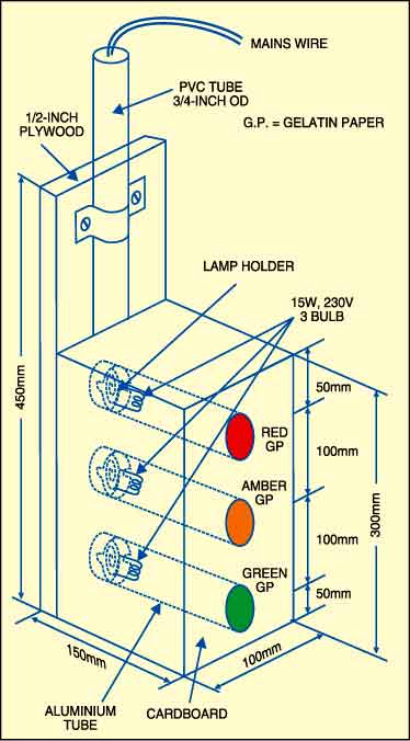
Make three tubes of thin aluminium sheet, which is readily available in hardware shops. The inner diameter of aluminium tubes should be such that these can snugly fit on the light sockets. Using a sharp knife, make holes opposite the sockets carefully. Wire the sockets at the back and take the wires out through the PVC tube.
First, fix three 15W bulbs (B1 through B3) and then press on the tubes. Support the other ends of the tubes in the holes made on the front panel of cardboard box. Sandwich gelatine papers of the three colours between two sheets of cardboard and fix over the tubes. The visibility of red, amber and green lights improves with their mounting on the tubular shape.
Also, check the density-based Traffic Light Controller using Arduino.

Most Best site in electronics
Thank you for your feedback.