


 Presented here is a simple circuit that will help you figure out whether a transistor is npn or pnp type. If the transistor under test is npn, red LED will blink. If it is pnp, green LED will blink. This circuit is highly useful for small labs where components lie on the desk unidentified after a project is done and it is very tedious to read the part number printed on the component and identify it from its datasheet. The circuit provides a straightforward method for identification of bipolar transistors.
Circuit and working
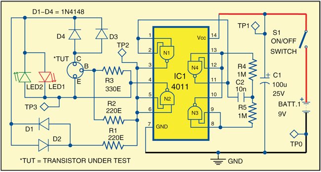
As shown in Fig. 1, transistor polarity checker circuit is built around quad 2-input NAND gate CD4011 (IC1), four diodes (D1 through D4) and a few discrete components. It works off 9V supply, and a PP3 battery is recommended for compactness of the unit.
A rectangular oscillator is made using gates N3 and N4, which is further connected to N1. The output of N1 is connected to the input of N2. Like this, you get square waves at the outputs of N1 and N2 that are 180 degrees out of phase.

Two LEDs (LED1 and LED2) are used to indicate the polarity of the transistor under test. These LEDs are connected to the outputs of N1 and N2 as shown in Fig. 1. If there is no transistor connected at TUT, both LEDs will blink alternately. If the transistor under test is pnp, it provides a short across the LEDs when the output of N1 is low, which does not allow the red LED to glow. When the output of N1 becomes high, the transistor under test (if pnp) stops conducting and the green LED glows. Thus the green LED blinks if the transistor under test is pnp.
Similarly, if the transistor under test is npn, it will provide a short across the LEDs when the output of N1 is high, which does not allow the green LED to glow. When the output of N1 becomes low, the transistor under test (if npn) stops conducting and the red LED glows. Thus the red LED blinks if the transistor under test is npn.
Download PCB and component layout PDFs: click here
Construction and testing
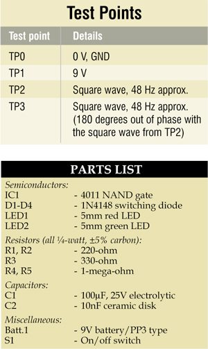
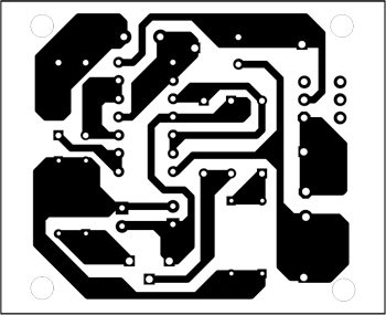
An actual-size, single-side PCB for transistor polarity checker is shown in Fig. 2 and its component layout in Fig. 3. Assemble the circuit on the PCB to avoid assembly errors. After construction, enclose the whole circuit in a suitable, small box. Connect a three-pin socket for inserting the transistors to be tested.
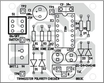
To test the circuit for proper functioning, check correct power supply at TP1 with respect to TP0. Check the waveforms at TP2 and TP3 as mentioned in the test points table.
The author is a regular contributor to EFY. He has many articles published to his credit in India and abroad
Hi, if I wanted to make an 18V version for testing proximity switches, what changes would I need to make? Just the resistors for the LEDs and maybe uprate the electrolytic I guess, as the NAND chip is good to 20V. Also, on the schematic, D3 and D4 are in the same orientation which I believe is incorrect but the layout has them in the correct orientation.
Hello, the project is very interesting, what does the bipolar ionizer circuit consist of, could you please describe thanks
Your query is not related to this project. Bipolar ionizer circuit generates high potential output and a low potential output. For more detail, you may refer this link : https://patents.google.com/patent/US20160211655