


 Presented here is a sensitive alarm using a vibration sensor for application as a simple surveillance system for protecting doors and windows. It can also be used as a luggage or locker protector. The circuit beeps and lights a white LED when it detects even a slight vibration. It is compact, battery-operated and can be enclosed in a small box.
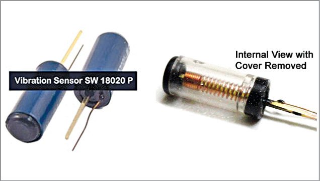
The circuit uses a miniature vibration sensor SW18020 P from Gaoxin. It can be used in different ways to sense mechanical vibrations to activate alarms and other surveillance systems in a variety of vibration-detection projects.
Vibration sensor
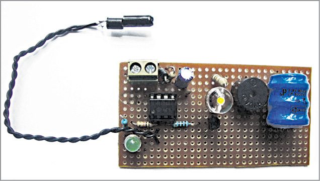
The vibration sensor has two electrical contacts that do not touch each other in idle condition. When any movement or vibration occurs, the sensor’s contacts close and touch each other. When the movement or vibration stops, the sensor’s contacts return back to their original positions, away from each other. The closed contacts during vibration trigger the circuit connected to it. The author’s prototype is shown in Fig. 1.

The vibration sensor has a small spring mechanism that makes the contacts touch each other when vibration occurs above a certain threshold level. Two pins coming out of the sensor are insulated by a resistance of more than 10-mega-ohm. During vibration the spring inside the sensor vibrates and makes a momentary short-circuit between the two terminals.
Terminals of the vibration sensor have no polarity but one pin is thick. It is connected to Vcc through a resistor and the thin pin is connected to the circuit to be triggered.

The sensor’s maximum working voltage is 12V DC but it works even at three volts. When using it in a circuit, it consumes less than 5mA current and offers around 10-mega-ohm contact resistance in open state and less than 5-ohm in contact state. It is highly reliable and its response time is less than 2ms. It works more than 500,000 times without breakdown. The vibration sensor is shown in Fig. 2.
Circuit and working
Circuit diagram of the vibration sensor is shown in Fig. 3. It is built around NE7555 timer (IC1), npn transistor BC547 (T1), piezo buzzer (PZ1) and a few other components.
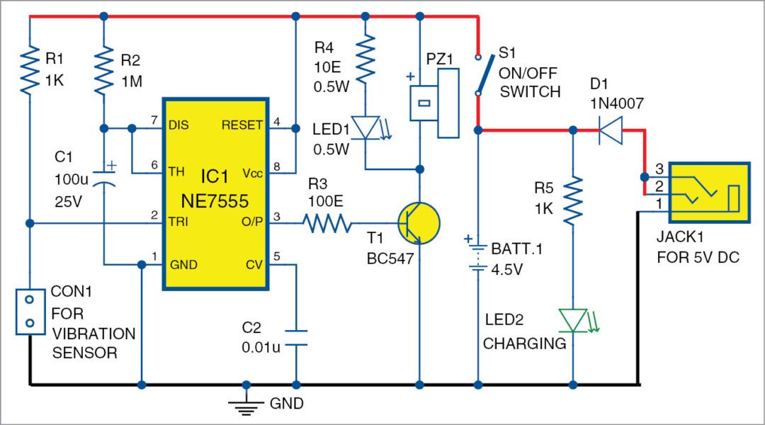
The circuit is simple. NE7555 timer is configured in monostable mode to activate the buzzer and the white LED for around two minutes when the sensor detects vibration. The vibration sensor is directly connected between trigger pin 2 and ground pin 1 of IC1. NE7555 is the CMOS version of NE555 timer and works off three volts.
The sensor is biased by resistor R1, which also keeps trigger pin 2 of IC1 in high state during standby. When the sensor senses a small vibration, its contacts close and takes pin 2 of timer to ground level. This triggers the timer and its output goes high for around two minutes based on the values of timing components R2 and C1. When output of the timer turns high, transistor T1 conducts to drive the 0.5W white LED and the buzzer.
The circuit is powered by a 4.5-volt rechargeable battery pack generally used in cordless phones. It can be charged using a mobile phone charger if a suitable socket is provided. LED2 indicates charging of the battery.
Construction and testing
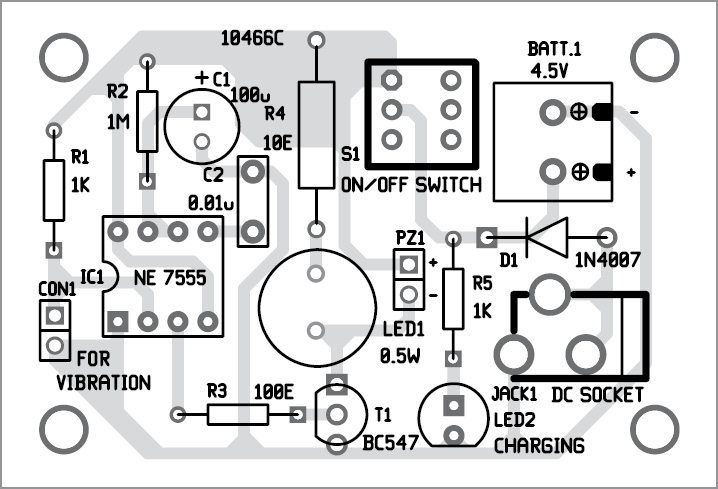
A single side PCB layout for the vibration sensor is shown in Fig. 3 and its component layout in Fig. 4. Assemble the circuit on the PCB and enclose in a suitable box.
Connect the vibration sensor to the circuit using connector CON1. Glue the sensor on top of the box if it is to be used as a luggage protector, or on the window or door if used as a vibration alarm.

Download PCB and Component Layout PDFs: Click here
The circuit works off a 4.5V battery. The 5V regulated power supply is required to charge the battery.

Mohan sir ന്റെ എല്ലാ circuit ക ളും വളരെ ഉപകാരപ്രദമാണ്. Thanks
what is the threshold value of force for vibrator to act? can you clarify please. assume a knock on the door.
how can we extend the project ,any ideas?
You can extend the project to use in Smart Home systems, Automotive devices, Communication devices, Electronic Scales, Instruments / Toys, Sports Equipment, etc.
The exact circuit design depends on the application. For example, with a slight tweak, you can replace buzzer and its driver section with audio amplifier and seapker to use it as an anti-theft system in your car/vehicle.
good project, can this be implemented for security, like fence wall,