


 There are several types of voice recorder and playback systems available in the market but most of them are expensive and their circuits are also very complex to assemble. Here is a simple voice recorder and playback system for recording and playback of voice messages. You can leave a voice message for your family or friends whenever you go out, which they can hear by pressing the ‘play’ button.
This voice recorder and playback system is built around a recording and playback chip that supports voice recording for 16 to 30 seconds and reproduces it clearly. It can be used in different types of applications such as door bells, railway announcement systems and automatic telephone answering devices.
Circuit and working
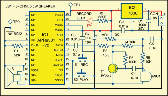
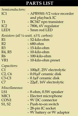
Fig. 1 shows the circuit of voice recorder and playback system. The circuit is built around voice recording and playback IC APR9301-V2 (IC1), voltage regulator 7806 (IC2), npn transistor BC547 (T1), 8-ohm, 0.5W speaker (LS1), electret microphone (MIC1) and a few other components.

IC APR9301-V2 is a high-quality voice recording and playback IC. The length of message recording depends on the value of external resistor R1 connected to its pin 7. The operation modes are described below.

Recording mode
When switch S1 is pressed, LED1 glows to indicate that recording has started. Now you can speak close to microphone MIC1 in order to record your message. You may have to vary VR1 to adjust for different microphones. IC1 remains in recording mode as long as switch S1 is pressed and pin 27 of IC1 is grounded. Recording stops after 20 seconds (selected by 52-kilo-ohm resistance in this case), pin 25 of IC1 becomes ‘high’ and LED1 stops glowing.
The recording time duration can be increased or decreased depending on the value of resistor R1 as follows:
1. 38 kilo-ohms for 16 seconds
2. 52 kilo-ohms for 20 seconds
3. 67 kilo-ohms for 24 seconds
4. 75 kilo-ohms for 30 seconds
Playback mode
When switch S2 is pressed momentarily, the recorded message plays from the start and can be heard from speaker LS1.
Standby mode
Pin 6 of IC1 is kept ‘low’ so that it returns to standby mode after the completion of recording and playback. If pin 6 is high, it will be in power-down mode and no recording or playback is allowed and current consumption is typically less than 1 µA.
Working of the circuit is simple. You can record your message for the duration defined by resistor R1 by keeping switch S1 pressed. Once recorded, the message can be played simply by pressing switch S2 momentarily.
Download PCB and component layout PDFs: click here
Construction and testing
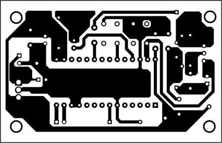
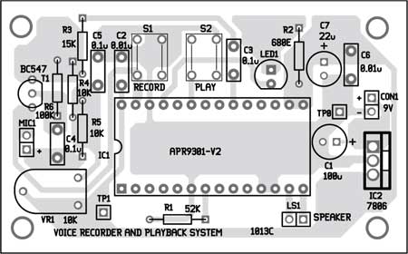
An actual-size, single-side PCB for the voice recorder and playback system is shown in Fig. 2 and its component layout in Fig. 3. Suitable connectors are provided on the PCB for connecting the microphone and speaker. Assemble the circuit on the provided PCB to minimise assembly errors. Carefully assemble the components and double-check for any overlooked error.
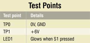
The circuit is simple and doesn’t need many test points to verify. Check the correct power supply at TP1 with respect to TP0. Press switch S1. If LED1 glows, it implies IC1 is working well.

Hello, Dear Sir
Thanks for this product. could you please send me a project that be able to select a track record of multi records?
Currently, we do not have the project/product for multiple track recording. But that can be built either using this voice IC in parallel or any other dedicated ICs or microprocessors.
good evening,
Can it play multiple times the recorded message?
Yes, you can play multiple times
I want to record for 1hr , can you please suggest me is there any way that I can do it?