


 Wireless power is transferred from transmitter to receiver coil using inductive coupling principle. For wireless power transfer to work efficiently, frequency of the transmitter and the receiver must be tuned to the same frequency. LC tank of transmitter side produces an oscillating magnetic field of the tuned frequency. LC tank of receiver side is same as the frequency of transmitter side, thus achieving high efficiency. Let us construct a wireless LED.
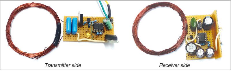
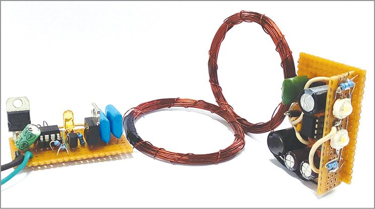
This wireless-powered LED can be used in mobile phone battery chargers, electric tooth brushes and low-powered loads such as LEDs, SMPSes, rotors and so on. The author’s prototype is shown in Fig. 1.
Circuit and working of Wireless LED
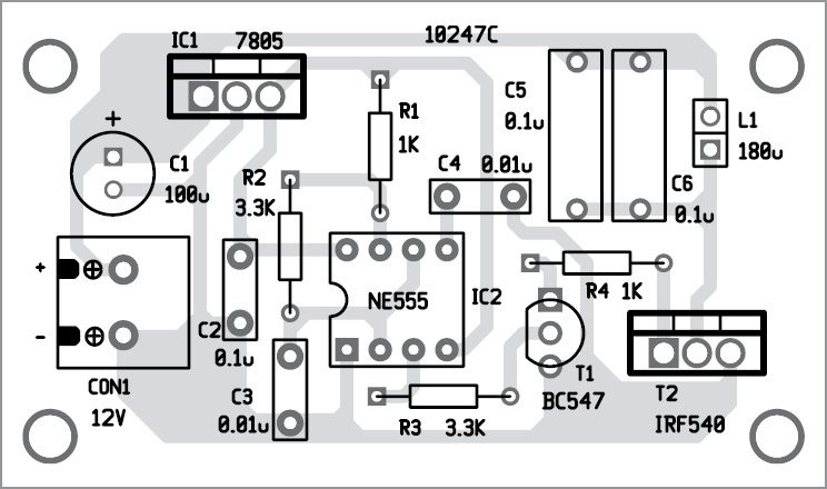
Circuit diagram of the transmitter unit is shown in Fig. 2. It is built around 5V voltage regulator 7805 (IC1), NE555 timer (IC2) and a few other components.

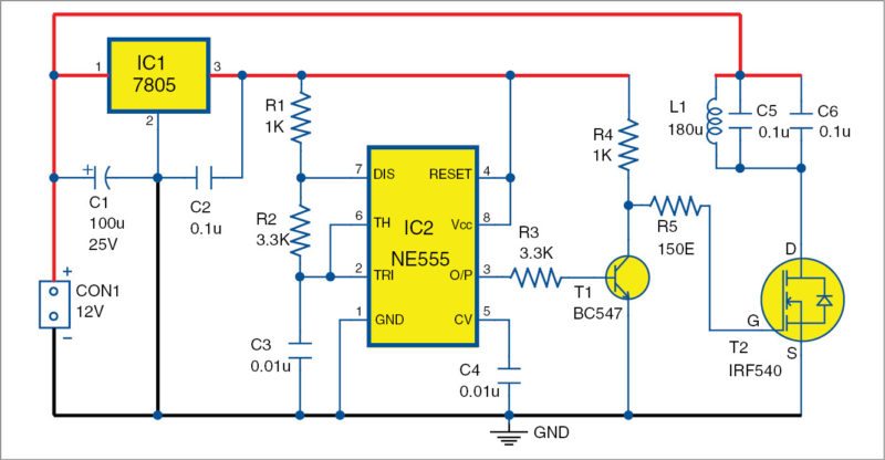
Positive voltage regulator 7805’s output provides regulated 5V for NE555 and BC547. NE555 is configured as an astable multivibrator for pulse generation. The capacitor charges through resistors R1 and R2.
Charging time t1 = 0.693(R1+R2)×C3
Discharging time t2 = 0.693(R2)×C3
Frequency of oscillation F = (1.44/(R1+2R2)×C3) = 18.94kHz
C4 is the bypass capacitor at control voltage pin 5 of NE555. T1 is the driver for power MOSFET IRF540 (T2). T2 drives LC tank circuit resonating at a frequency of F = 1/(2p(LC))
where, L = L1 = 180µH and C = C5+C6 = 0.1µF+0.1µF = 0.2µF
Therefore tuned frequency F is around 26kHz. It produces an oscillating magnetic field around the coil at a frequency of 26kHz linked with LC tank circuit of the receiver.
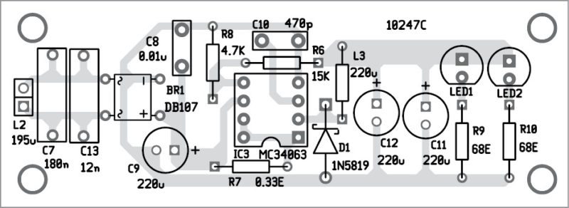
Circuit diagram of the receiver unit is shown in Fig. 3. It is built around buck/boost regulator IC MC34063 and a few other components.
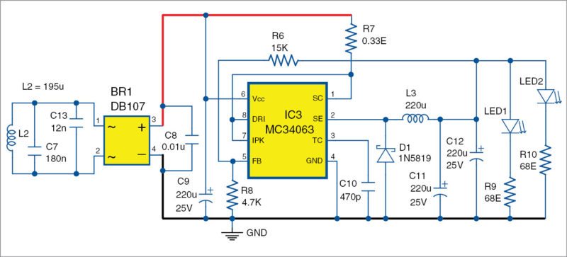
Inductor L2 and capacitors C7 and C13 form LC tank circuit tuned to the frequency of the LC tank on transmitter side. The frequency of the receiver LC tank is 26kHz using the frequency formula explained earlier.
BR1 bridge rectifier is used to convert high-frequency AC to pulsating DC. C8 and C9 are smoothing capacitors for providing regulated DC voltage. To achieve high efficiency, buck/boost chip MC34063 is used. It has wide input voltage range of 3V – 40V. Its maximum output current is 1.5A with an adjustable output voltage.
In this circuit, it is configured as a buck converter or step-down converter. Output (V_out) of the buck converter which appears at C11 and C12 with respect to ground, is calculated as V_out = 1.25V(1+R6/R8)
where, 1.25V is the internal reference voltage of MC34063 chip. So, V_out = 1.25V(1+15k/4.7k) = 5.2V, which is enough to drive power LEDs (LED1 and LED2).
R9 and R10 are the current-limiting resistors for LED1 and LED2.
Construction and testing
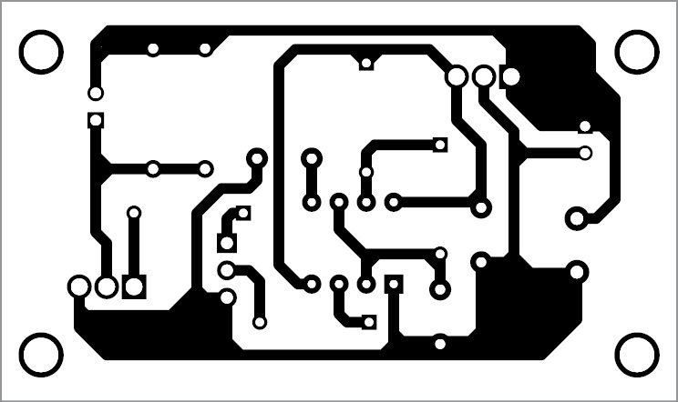
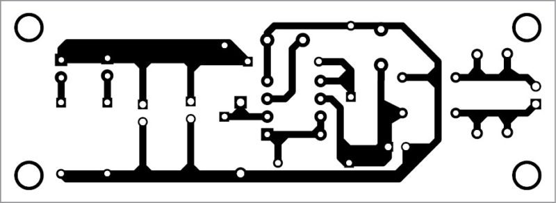
An actual-size, single-side PCB pattern for the transmitter unit for wireless LED is shown in Fig. 5 and its component layout in Fig. 6. Similarly, an actual-size, single-side PCB pattern for the receiver unit of wireless LED is shown in Fig. 7 and its component layout in Fig. 8. After assembling the circuits on the PCBs, enclose these in two separate boxes.
Load test. The receiver can deliver a load current of 271mA at 5.2V constant voltage.
Therefore approximate output power = 5.2V×271mA = 1.4W, and power consumption of transmitter = 12V×180mA = 2.16W (approx.).
When the receiver is away from the transmitter, power consumed by transmitter = 12V×20mA = 240mW.
Efficiency = output power/input power = 1.4/2.16 = 0.648 or 64.8%
Because of the air-core coils (less magnetic coupling), efficiency is low. It can be improved by using magnetic-core based coils.
Download PCB and component layout PDFs: click here
Visweswara Rao Kalla is an electronics hobbyist, interested in robotics, mechatronics, MCU programming, analogue and mixed-signal circuit designs

Can it done using other IC’s and farther range?
If possible…. I wanna know it..!
What is the appropriate distance between transmitter and receiver ?
At what distance will power transfer be most efficient?
Hi, great work.
how did you calculate the inductance of the receiver and transmitter coil? can I make the coils from a different size wire with the same inductance?
how can L3 inductor can do ?
Kindly elaborate your query.
At what points are you supposed to connect the copper coil too?
on the transmitter circuit
Hi, if I’m using 26AWG wire, how many turns would I want to do?
Sir can I increase the output voltage of the second circuit by 7 volts extra, that is I want 12 volts. If yes what is the changes I have to do. And what is the maximum distance between transmiter and receiver to keep the LED’s ON
The max power delivered to the receiving coil is 1.4w. Is it possible to transfer ~5-6W at the efficiency of 65% with this type of setup? I need 5v 1A on the receiving end i.e., 5w output power @65% efficiency is 8.3 w, with 12v input the max current draw should be 8.3/12 = ~.7A. Could you suggest such design?