


 This zener diode tester can be used to check zener diodes of 3.3V to 18V. The breakdown voltage of the unknown zener diode is indicated on the precalibrated dial of potmeter VR1. The tester can also identify the polarity of zener diodes.
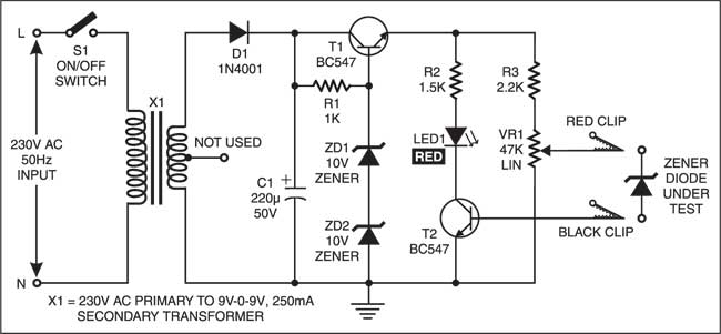
Zener Diode Tester Circuit
The power supply section comprising transformer X1, rectifier diode D1, filter capacitor C1, resistor R1, transistor T1 and zener diodes ZD1 and ZD2 provides approximately 20V DC stabilised voltage to the sensor section. The sensor circuit comprises resistors R2 and R3, potmeter VR1, red LED1 and transistor T2.
When linear potmeter VR1 is adjusted such that the voltage at its wiper arm (red crocodile clip) exceeds the breakdown voltage of the zener diode, the zener diode conducts and applies the bias voltage at the base of transistor T2, which causes red LED1 to light up. When the voltage at the wiper arm (red clip) is less than the breakdown voltage, the zener diode does not conduct and red LED1 does not glow.

For calibration of the zener diode tester, initially set the pointer knob of potmeter VR1 towards zero-resistance position. Short red clip of the potmeter and black clip of the transistor and switch on the tester. Rotate the pointer knob of potmeter VR1 slowly in clockwise direction until LED1 just starts to glow. Mark this setting of the knob on the paper dial as 0V.
Now connect a known zener diode of 3.3V between both the clips (red clip to the cathode and black clip to the anode of the zener diode) as shown in the figure. Rotate the knob of potmeter VR1 further in clockwise direction until LED1 just starts to glow. Mark this setting of the knob on the paper dial as 3.3V. Likewise, calibrate ity and rotate the knob of potmeter VR1 until red LED1 just starts to glow. The voltage shown by the pointer knob on the dial at this setting is the breakdown voltage value of the zener diode under test.
Note
If the zener diode is connected in reverse polarity (red clip to the anode and black clip to the cathode), the LED glows brightly at all settings of the knob above the zero reading, indicating that the zener diode is wrongly connected. The anode and cathode terminals of rectifier diodes can also be identified in this way. Do not touch the clips while testing.
The article was first published in April 2004 and has recently been updated.
