


 Using this simple Zener value evaluator circuit and a known-value zener diode, you can find the breakdown voltage value of any zener diode. The circuit is divided into two sections: zener evaluator and display unit. Regulated 12V and 5V are required to power the zener evaluator section, while the display section works off only 5V. Connect +5V, point A and ground of the zener evaluator section to the respective terminals of the display section.
Zener value evaluator circuit
The zener evaluator circuit comprises a linear ramp generator built around timer NE555 and an astable multivibrator built around another NE555. The resistor of the monostable is replaced with a constant-current source formed by transistor T1. Capacitor C2 is charged linearly by the constant-current source formed by transistor T1.
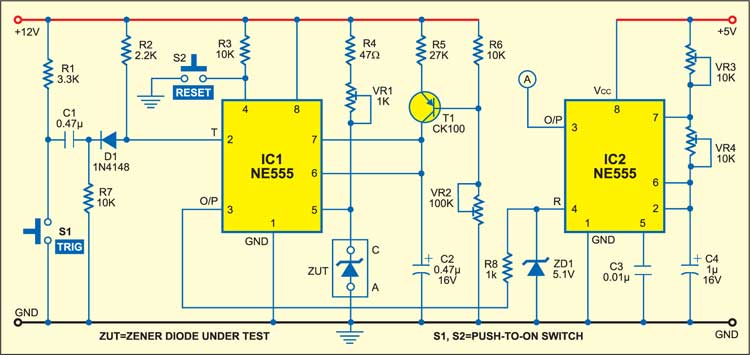
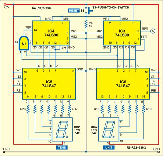
The time period T of the linear ramp generated by IC1 at its pin 6 across capacitor C2 is given by:

On substituting the values shown in Fig. 1, you get:
T= 0.15 second (approx.)
This value is equal to Ton of the monostable without connecting the zener at the control voltage terminal pin 5.
Now connect the zener to the control voltage terminal and trigger the monostable (IC1) by momentarily pressing switch S1. The output pulse width of IC1 is fed to the astable multivibrator (IC2). The time period of the astable multivibrator is around 7 milliseconds (ms) and it oscillates as long as the ramp output of IC1 is high.
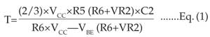
The display unit comprising decade counter ICs 74LS90, decoder/driver ICs 74LS47 and 7-segment common-anode displays LTS542 is shown in Fig. 2. Decade counters IC3 and IC4 count the frequency applied on clock pin 14 of IC3 from pin 3 of IC2.
IC 74LS90 is a 4-bit ripple decade counter. When the output of IC3 is ‘10’ (1001), it provides clock at pin 14 of IC4 (via AND gate N1) for further counting. For resetting IC3 and IC4, simply press reset switch S3 momentarily.
The outputs of decade counters IC3 and IC4 are connected to 7-segment decoders/drivers IC6 and IC5, respectively, which, in turn, are connected to common-anode displays DIS1 and DIS2 for displaying the frequency of astable multivibrator IC2 used to evaluate the unknown value of the zener diode.
Circuit operation
Let’s say the counter counts up to N1 for the known zener diode breakdown voltage value X1 and up to N2 for the unknown zener diode value X2. Now, you can calculate the value of the unknown zener diode from the following relationship:
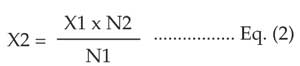
Suppose you have a zener diode rated at 6.8V (X1). Insert it at the position marked ‘ZUT’ of Fig. 1 and press trigger switch S1 momentarily. The counter counts up to, say, ‘29’ (N1), which is shown on the display. Now remove the 6.8V zener and insert the zener of unknown value (X2). The display now shows, say, 15 counts (N2).
From Eq. (2), the value of the unknown zener (X2) can be calculated as 3.5V.
The article was first published in October 2005 and has recently been updated.