Since its introduction several years ago, the Hall effect sensor has captured the imagination of design engineers. Being solidstate, it is a more reliable approach than electromechanical counterparts. Since the Hall effect sensor has no moving parts, low-level loads last well beyond billions of operations. There are many applications of Hall effect sensors. However, selection of the proper type is critical for any application.

What’s a Hall effect sensor

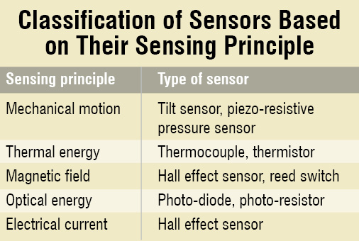
Sensors can be classified based on the physical effects that they can respond to. Hall effect sensors are unique in that their principle of operation is based on mixed effects.
When a current-carrying conductor is placed into a magnetic field, a voltage is generated perpendicular to both the current and the field. This principle is known as the Hall effect. So Hall effect sensors depend on the electric current as well as the magnetic field.
Typically, a Hall effect sensor has three wires or terminals: one for ground, one for supply (or reference) voltage and one for the output signal. The supply voltage is necessary to create the switching effect that takes place inside the sensor.
In practice, the basic magnetic field sensor—Hall element—is constructed from a thin sheet of conductive material with output connections perpendicular to the direction of current flow. When subjected to a magnetic field, it responds with an output voltage proportional to the magnetic field strength. The voltage output is in micro-volts (μV) range and requires signal conditioning electronics to achieve useful voltage levels.
The additional electronics needed is a differential amplifier and a temperature compensation circuit. Voltage regulation is also required when operating from an unregulated supply. When the Hall element is combined with this associated electronics, it forms a ready-to-use Hall effect sensor, which is an integrated circuit chip that contains a Hall element and the signal conditioning electronics.
According to Honeywell’s Hall Effect Sensing and Application, although Hall effect sensor is a magnetic field sensor, it can be used as the primary component in many other types of sensing devices. If the quantity to be sensed incorporates or can incorporate a magnetic field, a Hall sensor will perform the task.
In a sensing device, the Hall sensor senses the field produced by the magnetic system. The magnetic system responds to the physical quantity to be sensed (temperature, pressure, position, etc) through the input interface. The output interface converts the electrical signal from the Hall sensor into a signal that meets the requirements of the application.
Analogue and digital output
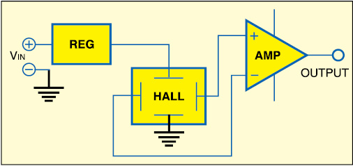
In an analogue (linear) output sensor, the output voltage is proportional to the magnetic field to which it is exposed. The sensed magnetic field can be either positive or negative. As a result, the output of the amplifier is either positive or negative, thus requiring both plus and minus (dual) power supply.
To avoid the requirement for a dual power supply, a fixed offset (or bias) is introduced into the differential amplifier. The bias value appears on the output when no magnetic field is present and is referred to as a null voltage. When a positive magnetic field is sensed, the output increases above the null voltage. Conversely, when a negative magnetic field is sensed, the output decreases below the null voltage, but remains positive.
In brief, continuous-time, ratiometric, linear Hall effect sensors are optimised to accurately provide a voltage output that is proportional to an applied magnetic field. These are well-suited for use in position sensing systems, for both linear target motion and rotational target motion.
Hall effect sensors are sometimes referred to as ‘switches’ rather than ‘sensors’ because of the on-off ‘digital’ voltage signal they output. A digital-output sensor has an output that is just one of two states—‘on’ or ‘off.’
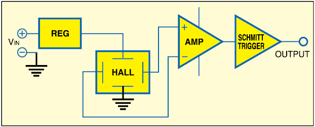
The basic analogue-output structure can be converted into a digital-output structure with the addition of a Schmitt trigger circuit with hysteresis (see Figs 1 and 2). The Schmitt trigger compares the output of the differential amplifier with a preset reference. When the amplifier output exceeds the reference, the Schmitt trigger turns on. Conversely, when the output of the amplifier falls below the reference point, the output of the Schmitt trigger turns off.
Usually, digital-output types are widely used as contactless switches in consumer products. One example is the cover switch in clam-shell cellphones.
Omnipolar and unipolar
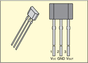
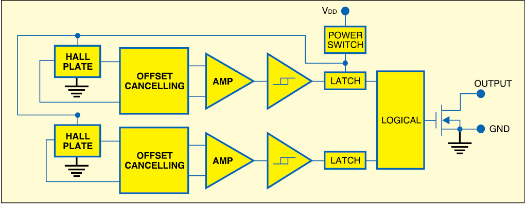
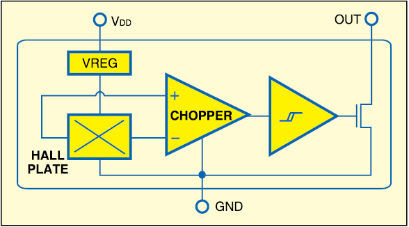
Fig. 3 shows the functional block diagram of an omnipolar (north- or south-pole) Hall effect switch. It is based on two Hall effect plates and a chopper-stabilised architecture. The single open-drain output switches on with either a north-pole or south-pole magnetic field of sufficient strength. When the magnetic flux density (B) is larger than operate point (Bop), the output switches on (output pin is pulled low). The output turns off when B becomes lower than the release point (Brp). It remains off when there is no magnetic field.
In case of a unipolar Hall effect switch (refer Fig. 4), the output switches on in the presence of a sufficiently strong south-pole magnetic field facing the marked side of the chip package. Similarly, the output switches off in the presence of a weaker south field and remains off with no field.
Unipolar types are optimised for applications of solidstate switches. Magnet proximity sensor for reed switch replacement in low-duty-cycle applications is a good example.
Transfer function

The transfer function of a device describes its output in terms of its input. For analogue-output Hall effect sensors, the transfer function expresses the relationship between a magnetic field input (in gauss; unit of magnetic flux density equal to 1 maxwell per square centimetre) and a voltage output.
The principal input/output characteristics of the digital-output Hall effect sensor are operate point, release point and the differential. As the magnetic field is increased, there is no change in the sensor output until the operate point is reached. Once the operate point is reached, the sensor changes state to ‘on’. Further increase in the magnetic input beyond the operate point will have no effect.
If the magnetic field is decreased below the operate point, the output remains the same until the release point is reached. At this point, the sensor’s output returns to its original state (off).
The purpose of the differential between the operate and release points is to eliminate false triggering caused by minor variations in the input.
Practical applications
Hall effect sensors are widely used for speed, linear position, linear angle and position measurement in automotive, industrial and consumer applications. These devices can be used to sense many physical parameters—ranging from direct measurement of a magnetic field to detection of ocean currents. Hall effect sensors have been successfully used in linear-output applications such as current sensing (motor control protection and disk drives), position sensing (contactless potentiometers and brushless DC motors) and encoded switches (rotary encoders).
Digital-output applications include lens position sensors, proximity sensors, pressure sensors, limit switches, door interlocks and vending machines.
The author is a freelance writer and regular contributor to EFY