Power conversion is vital in modern electronics because we regularly switch between AC and DC power. Main power sources normally supply AC power, whereas batteries give DC power. However, switching AC to DC with a rectifier is typically more convenient than constantly replacing batteries. A rectifier is an electrical device that converts alternating current (AC) to direct current (DC), which is widely seen in many of our everyday gadgets.
A single-stage rectifier, on the other hand, does not provide smooth, usable DC; a steady DC output requires multistage rectification and additional filtering circuitry. Here’s an explanation of how half-wave and full-wave rectification function.
Half and Full Wave Rectification Basics
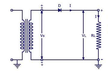
The simplest rectifier is a diode connected to AC power supply. This is also known as a half wave rectifier. A simple half wave rectifier is a single p-n junction diode connected in series to the load resistor. The operation of a half wave rectifier is easy to understand a p-n junction diode conducts current only when it is forward biased.
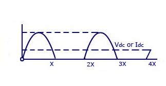
This principle is used in a half wave rectifier to convert AC to DC. The cycle of the input provided here is alternating current. This input voltage is stepped down using a transformer. A p-n junction diode conducts current only when it is forward biased. The same principle is made use of in a half wave rectifier to convert AC to DC. The input here is an alternating current. This input voltage is stepped down using a transformer. Since the diode is forward biased for half cycle of the AC, the output is available only during that half cycle.
To reduce the ripples in the rectifier circuit with capacitor filter:
- RL should be increased.
- input frequency should be decreased.
- input frequency should be increased.
- capacitors with high capacitance should be used.
Full-Wave Rectifier
Like the half wave circuit, a full wave rectifier circuit produces an output voltage or current which is purely DC or has some specified DC component. Full wave rectifiers have some fundamental advantages over their half wave rectifier counterparts. The average DC output voltage is higher than for half wave, the output of the full wave rectifier has lesser ripple than that of the half wave rectifier producing a relatively smoother output waveform.
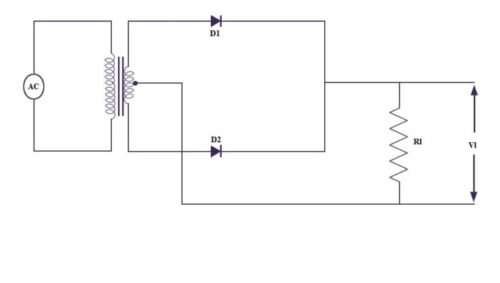
There are two major types of full wave rectifier designs used frequently. The smaller design uses two diodes instead of the single diode used in half wave diode, i.e. one for each half of the cycle. A multiple winding transformer is used where secondary winding is split equally into two halves with a center tapped connection. The connection for a center tapped full wave rectifier are shown below.
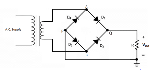
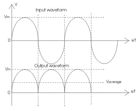
Another configuration requires four diodes connected in an H-bridge configuration. The four diodes labelled D1 to D4 are arranged in “series pairs” with only two diodes conducting current during each half cycle. During the positive half cycle of the supply, diodes D1 and D2 conduct in series while diodes D3 and D4 are reverse biased and the current flows through the load. During the negative half cycle of the supply, diodes D3 and D4 conduct in series, but diodes D1 and D2 switch “OFF” as they are now reverse biased. The current flowing through the load is the same direction as before.
Filtering the Rectified Voltage
The output across the diodes in the above steps is neither complete nor is it completely DC. The output is not steady DC and is not practical to use with circuits. A filter circuit also known as a smoothing capacitor is added to the rectifier circuit to improve the output. Smoothing capacitors are connected in parallel with the load across the output of the full wave bridge rectifier. This filter circuit increases the average DC output level as the capacitor acts like a storage device. The smoothing capacitor converts the rippled output of the rectifier into a smoother DC output.
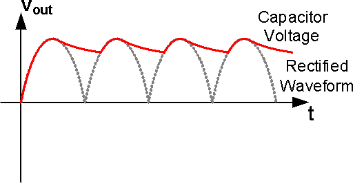
However, there is still a minor ripple in the output can be smoothened out by the varying the capacitor values. The ripple voltage is inversely proportional to the value of the smoothing capacitor. These two are related by the following formula:
Vripple = Iload/(fxC)
An alternative is to use a voltage regulator IC for a constant DC power supply.
What is Form Factor?
The form factor is the ratio of RMS value to the DC value.
The form factor of a half-wave rectifier is equal to 1.57 and for full-wave rectifier is 1.11.
Enhancing Rectifier Efficiency and Performance
- Efficiency: Full-wave rectifiers are more efficient than half-wave rectifiers because they use both sides of the alternating current waveform, supplying greater power to the loads.
- Applications: Rectifiers are essential in power supply for devices such as radios, televisions, battery chargers, and power converters because they convert household alternating current to usable direct current.
- Thermal Considerations: Diodes in rectifiers can overheat, especially under high loads. Proper heat dissipation, such as heatsinks or fans, may be required to sustain performance.
Half Wave Vs Full Wave Rectifier
| Feature | Half-Wave Rectifier | Full-Wave Rectifier |
| Number of Diodes | 1 diode | 2 diodes (center-tap) or 4 diodes (bridge configuration) |
| Efficiency | Lower efficiency (~40.6%) | Higher efficiency (~81.2%) |
| Output Frequency | Same as input AC frequency (f) | Double the input AC frequency (2f) |
| Ripple Factor | Higher (1.21) | Lower (0.48) |
| DC Output Voltage | Lower DC output voltage | Higher DC output voltage |
You can check out constructing of a Full Bridge rectifier here with a video tutorial:


Awesome
Thank You for your feedback.
Fantastic
When use an transformer with center tapped connection and full bridge rectifier may obtain +V, and – V from GND ( the center tapped connection), it is an interesting connection to be mentioned…