


This buyers’ guide explains how desktop manufacturing equipment can be used for full product realisation and to understand how production considerations inevitably impact the design process. When designing a product the most important factor is defining a product’s success. However, with advancements in desktop manufacturing, most parts can now be produced in-house, which saves a lot of time.
Presented in this article are the different technologies and buying tips for the most popular types of desktop manufacturing equipment. For a new product, the first thing is the product realisation process, which encompasses the entire cycle of production and mechanical design so that all components including assembled printed circuit boards (PCBs), are designed to fit into the mechanical design.
Then, if everything is okay, PCB designs are verified and finalised and their Gerber files are sent for production of the PCBs to the PCB manufacturer. Sometimes, manufacturers may revise these files before they proceed further. Also, they may provide turn-key solutions, where they make PCBs, source components, make stencils and assemble PCBs, all at one place to save time, in order to meet the pace of the market.

Key factors involved in PCB manufacture
Basic equipment for PCB production on the basis of the board as input are the screen or stencil printer, pick-and-place machine, reflow oven, board DE-fluxing machine, stencil cleaning machine and automated optical inspection system. Steps involved in producing a PCB are:
1. The screen printer applies solder paste to the PCB on pad locations.
2. The pick-and-place machine picks up, inspects and puts surface-mount technology (SMT) components in a particular position on programmed locations.
3. Board DE-fluxing and stencil cleaning machines are used for cleaning the PCB and stencil, respectively.
4. Automated inspection equipment are used for inspection of the assembled PCBs for detection of any wrong placement or missing components.
Electronics manufacturing using SMT is a method in which electronic components are assembled with automated machines that place components on the surface of a board. The process involves making the PCB and assembling the components on that PCB.
After checking availability of various types of desktop manufacturing equipment, you should consider the various types available and be familiar with the associated pros and cons. All PCB prototyping work can be done in-house and time-to-market can be reduced.
Selection criteria
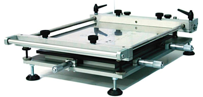
Stencil printers. The first stage of automated assembling of PCBs is stencil printing. For this we require stencil, solder paste and printer. Components are either leaded or SMT soldered to the board and exposed areas of the board are tinned or plated with solder. Stencil printers are available in three configurations, as given below:
Manual. Simple printing devices are suitable where high-precision alignment of a stencil-PCB is not critical. These are suitable for low volumes of up to 150 boards per day.
Semi-automatic. Loading and unloading of PCBs is done manually in this case. These as suitable for professional electronics products with medium volumes of up to 500 boards per day.
Fully-automatic. These are used for precision and in-line high-volume production of more than 500 boards per day.
Nearly 85 per cent of the defects produced in an SMT production line result primarily from the printing process. Careful selection of the printer is therefore imperative. Major considerations for selection of stencil printers are explained below:
Maximum size. Maximum size of the PCB the printer can handle; length and breadth expressed in millimetres
Minimum size. Minimum size of the PCB the printer can handle; length and breadth expressed in millimetres
PCB thickness. Lower and higher limits of the PCB; specified in millimetres
Stencil size. Maximum and minimum size of the stencil; length and breadth specified in millimetres
Printing accuracy. Specified in millimetres and Sigma limits
Cycle time. Standard printing time under optimum condition specified in seconds
Printing mode. Single- or double-side printing
Cleaning system. Dry/wet/vacuum
Operation system. For the integral computer
Automated SMD pick-and-place machines. SMT component placement systems, commonly called pick-and-place machines, are used for placing surface-mount devices (SMDs) onto a PCB. These are also capable of placing of a broad range of electronic components like capacitors, resistors and integrated circuits onto the PCBs from tapes and trays at a high speed with a high degree of precision.
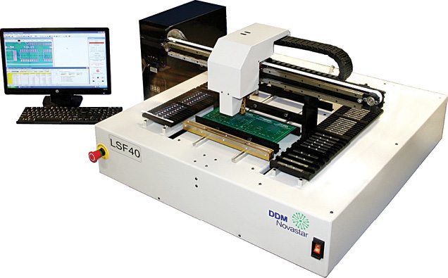
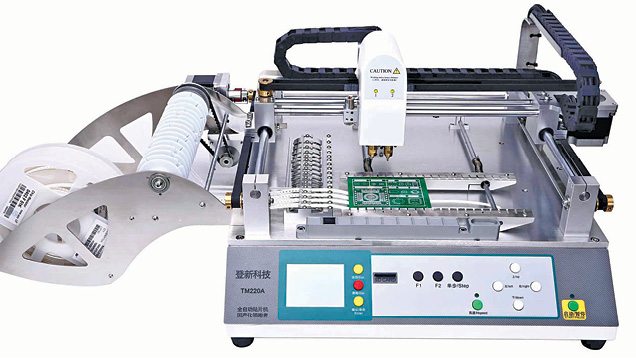
Benchtop pick-and-place models offer low-cost solutions for low- to medium-volume SMT placement applications. Selection of the machine is normally based on the following parameters:
Placement rate. Capacity of placing a number of components in one hour; specified as components per hour (CPH)
Placement accuracy. Accuracy of placing components at designated place on the PCB; specified in µm and Sigma limits
Component size. Dimensions of length and breadth specified in millimetres
Minimum. Minimum size of component that can be handled
Maximum. Maximum permissible size of components the machine can pick and place
Minimum component lead pitch. Distance between two adjacent leads; specified in millimetres
Range of components. Capability of placing a variety of components such as LEDs, ball-grid arrays, quad-flat packages and SMT connectors
Picking modes. Capability of picking parts from tapes, tubes or trays and loose components
Software. Windows-based, user-friendly
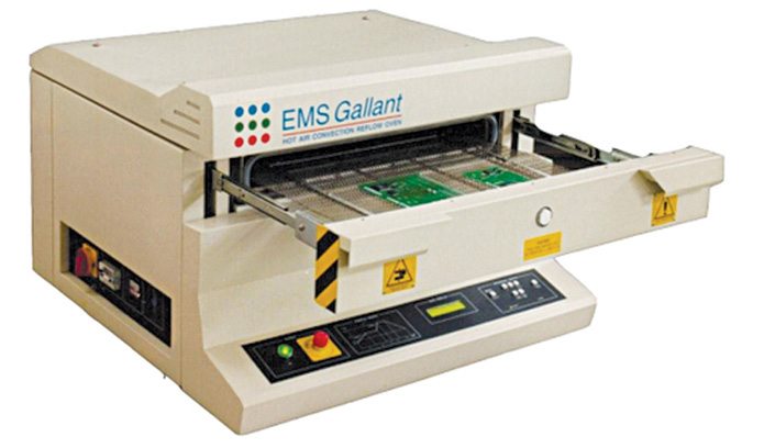
Reflow ovens. Reflow soldering is a process in which solder paste, which holds components temporarily to their contact pads on the PCB, melts and reflows when subjected to controlled heat, thereby permanently connecting the components to pads. There are two types of reflow ovens: infrared (IR) and convection.
In IR reflow ovens, heating is achieved by using IR ceramic heating elements. When assemblies are moved in a specified direction constantly into the conveyors, radiating elements heat the components and heat is moved to the solder paste.
In convection reflow ovens, the PCB is transported through a conveyor system. It has multiple zones, which can be individually controlled for temperature.
Selection criteria for a desktop model of the reflow oven are given below:
Welding requirement. Able to satisfy all welding specifications of 0201 resistance and capacitance, fine spacing QFP, SOP, PLCC, BGA and CSP.
Size of oven. Able to consistently reflow product at required speed to meet production needs
Maximum board width. Maximum size of PCB the machine can handle
Heating supply. IR ray or hot-air convection
Temperature-control segments. Maximum number of segments that can be set and controlled for temperature; control can be manual or using a PC
Welding time. Time taken for completion of welding of one board; expressed in minutes
Compatibility. Lead and lead-free reflow applications
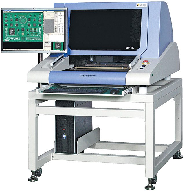
Automatic or automated optical inspection, or AOI. This is an essential tool in an integrated electronics test strategy. It helps in fast and accurate inspection of PCBs to ensure that the PCBs leaving the production line have been assembled correctly and without manufacturing faults. The AOI machine is normally placed into the production line just after the soldering process, so that the defective card is removed from the assembly line at an early stage. The machine should be able to detect soldering and component defects. Specifications for evaluation and selection of an AOI are given below:
Throughput. Area scanning capability per second; number of components scanned per hour
Maximum board size. Maximum dimension that can be scanned; specified in length x breadth in millimetres
False calls. Percentage of false detection (<0.05% typical)
Component. Position, condition, wrong polarity, alignment skewed, leads bent or lifted and wrong value
Solder. Bridging, open, insufficient or short solder balls
Algorithms. Should be able to scan components based on colour and barcode
Programming skill level. Engineer, technician or operator
Operating system. Of integral computer
Assembled desktop 3D printer. One area that remains largely unexplored is the use of additive manufacturing for electronics. Due to the complexity involved, development of 3D printers in the electronics industry is still in its infancy. Once convergence of electronics and 3D printing matures, it will have staggering implications on PCBs and rapid prototyping.
While it is unlikely that 3D printers for electronics will replace all traditional processes for in-house development of high-performance electronic device applications, these will be particularly useful in rapid prototyping.
Buying tips
Facilities offered by a machine need to be carefully analysed by matching these against costs to ensure that the choice made is correct for the particular production environment. General selection criteria and buying tips for selection, which are applicable to all equipment and processes, are as under:
Nature of business. Whether you want to be an original equipment manufacturer or contract/custom manufacturer, or both.
Profile of the product. Relates to parameters of the board including size, complexity, components density and range of components to be mounted on the board; setup for manufacturing of a motherboard vastly differs from that of the control card of an AC.
Volume of production. Manually-operated machines are unsuitable for high-volume production. On the other side, fully-automated ones are expensive in terms of initial as well as running costs.
Quality of product. Machine and process should make the product meet industry or military standards.
Reliability. Once setup is placed into service, it is critical that it remains operational. Equipment in the setup therefore should withstand the rigors of production. Maintenance downtime should not be overlooked. Maintenance requirements should be compared carefully before selecting the equipment.
Life cycle. Machine should provide seven to ten years of service.
Vendor credibility. Credibility of manufacturer or vendor is of utmost importance. Their experience, standing in the market, provision of training facilities, clause of maintenance support, location of service centres, provision of field service and availability of spares are some aspects that must be considered.
Conclusion
Manufacturing setups for assembling PCBs are very expensive in terms of initial and running costs. These are available from highly-integrated as one setup to an ensemble of stand-alone machines. Once established, the facility must remain operative for all times except when under maintenance. It is therefore imperative that evaluation of machines is done on the basis of the nature of business, volume of production, profile of product and dependability of the vendor.
Do you like this article? You may also like these buyer’s guides.
Nidhi Kathuria is a senior application engineer at EFY Labs, New Delhi

I like to subscribe