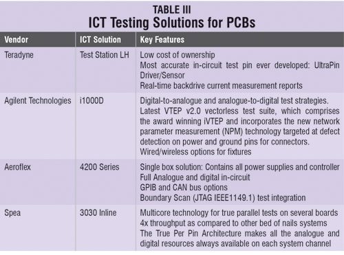
 ICT systems gain direct electrical access to the components on a PCB via an electromechanical ‘bed of nails’ fixture and test for manufacturing faults. Advancements in ICT systems have contributed towards lowering overall manufacturing test costs by improving fault coverage, reliability and throughput of in-circuit production tests.
 Fully automated ICT systems having compact size and integration with high-volume production lines minimise the need for operator handling. This saves labour costs and reduces the risk of product damage due to electrostatic discharge (ESD). Capabilities of ICT systems have advanced far beyond when they were first introduced. Now, with all the additional electrical test capabilities that do not require actual physical test access, we can categorise today’s versatile test systems as ‘electrical test controllers’ rather than ‘in-circuit testers.’
“Although ICT is appreciated for component-level testing, testing of components that are connected in parallel is almost impossible,” adds T. Anand, managing director, Knewron.

ICT to ETC transition. ICTs have been popular since long due to their usage in high-volume production environments, mostly for simple tests. “However, ICT is the most tedious, cumbersome and expensive type of testing. Creating an ICT fixture is costly and time-consuming activity. It is typical example of White Box (Glass Box) testing. Now, electrical test controllers (ETCs) aka automated test controllers ATCs do much better job than ICTs. Their testing method can be categorised as Black Box (full function) testing too,” says T. Anand.
ETCs do excellent job in simulating end-user, which gives more valuable information than ICTs. In short, ICTs have grown up to be ETCs.
Typical digital ICTs deploy boundary scan technique and perform basic digital verification, unlike ETCs where test case is generated, voltage/data is applied to respective pins and output is read and verified.
Boundary scan
Boundary scan is the unique solution to many test requirements and provides information about the board without accessing the complete board. It is ideal for testing those complex boards that could not be tested otherwise due to lack of test access.
 Boundary scan systems have little hardware and their significant part is software. The well-established test technique boundary scan JTAG IEEE Std. 1149.x requires test program to be generated before it can be used. Being an integral part of a boundary scan system, test program generator uses the net list of the unit under test and the BSDL files of the boundary scan components contained within the circuit to create test patterns for the rest. The test program generator also creates test vectors that enable the system to detect faults on the nodes and non-boundary scan components that are surrounded by boundary scan devices.
Functional automated test
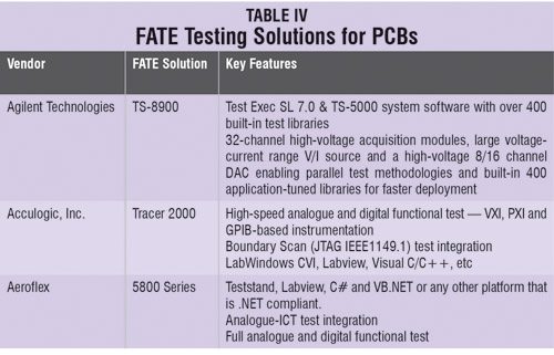 Digital boards are well suited for testing with functional automated test (FATE) systems where much of the program can be generated automatically by entering the circuit data into the tester, which builds up its own picture of the circuit and then, with knowledge of the pin connections, it can build up a test program for the board. The simulations can reveal design problems such as race states or even the non-required circuitry. Unfortunately, the program generation usually needs a lot of finishing, which is a time-consuming process. Also, the analogue areas often require analogue-measuring instruments to be used and need to be programmed manually. This manual programming can be very expensive to implement.
Although, FATE systems can be very fast at finding functional faults with a board, they are not always so fast in finding the problem area. In most cases they are unable to locate a problem because of lack of view of the internal areas of the board. A guided probe can be connected to the tester that can be manually applied to different points on the circuit under program control to check the points on the board that are not accessible via the bed of nails. Again, in the case of analogue areas, the routines required for fault finding using guided probe need to be programmed manually, which can be particularly time consuming.
Design for testability
Boundary scan—and any other test technology—requires design rules that must be considered. If such design rules are disregarded, the achievable test depth might be considerably affected, or in extreme cases, completely lost. “Nothing is ‘sadder’ than a board that cannot be tested because of one missing interconnection. But there’s no need to worry about possibly ‘many’ design rules. Convenient software provides support for rule compliance,” adds Harish. Moreover, it once again demonstrates that it makes sense to start with test generation at a very early stage of product design. Once the layout is finalised, things are relatively hard to change.
Pankaj V. is a technical journalist at EFY, Gurgaon, while Dilin Anand is senior technical correspondent at EFY Bengaluru. You can read the full story on www.electronicsforu.com in the Test and Measurement section