For quicker measurement, control and data analysis in professional engineering labs
EDWIN HOH
The demand for test and measurement instruments to meet the lab infrastructure needs of professional engineering colleges is inevitably on the rise. To cater to various engineering fields offered, labs are equipped with a multitude of test and measurement instruments ranging from high-end oscilloscopes and spectrum analysers to common equipment such as digital multimeters and power supplies.
Traditionally, measurements are taken from a single instrument one at a time, recording the values. The measurement data is transferred to a PC to perform further data analysis. However, today, when measurements have become complex and integration of multiple instruments is required, this method is impractical as it is time-consuming and inefficient. Educators are therefore looking at integrating instruments into lab stations so that various tasks such as measurements, data analysis and data storage can be performed in a single PC.
Building an automated lab station
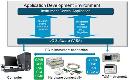
Building an automated instrument lab station requires consideration of three major components, namely, the software, hardware connectivity and instruments (see Fig. 1). The software on a PC is used to control the instrument that is connected to it using a connectivity hardware via an instrument control bus. Understanding each of these components helps in deciding which option is best suited for your application. Key considerations when building such a system are the ease of connectivity and scalability, performance and reliability.

Software. The first component to consider in designing an automated lab station is the software. It consists of three sub-components: The application development environment (ADE), instrument driver and input/output (I/O) software.
The ADE can either be a textual (C++, C# and VB.NET) or graphical programming language (National Instruments’ LabVIEW and Agilent’s VEE). In deciding which ADE is the most suitable for your application, factors such as the learning curve, ease of integration with other software and hardware, robust data analysis and management, reporting capabilities and support and maintenance costs are important.
The instrument driver is essentially a set of software routines that allows quick communication with an instrument. Each routine corresponds to a programmed operation, such as configuring, writing to, reading from and triggering the instrument.
Two types of instrument drivers are prevalent today: Interchangeable virtual instrument (IVI) driver and plug-and-play drivers. The IVI standards specify an instrument driver architecture that provides compatibility with popular ADEs, common command syntax across instrument families and members and supports PC industry standards like COM (Component Object Model). The two architectures of IVI drivers are IVI-COM, which is based on Microsoft’s COM standard, and IVI-C, which is based upon VXIplug&play specifications. Both IVI-COM and IVI-C consist of a set of instrument classes and provide instrument interchangeability independent of the instrument vendor.
[stextbox id=”info” caption=”Available automation software”]
Agilent VEE. Agilent VEE (Visual Engineering Environment) is a high-level object-based dataflow graphical programming software for automated test, measurement, data analysis and reporting. It is designed to work seamlessly with T&M instruments and comes packed with all the desired features for an educational lab station, such as ease of connection to various software and hardware devices from multiple vendors, data manipulation and display utilities, runtime deployment capability and built-in MATLAB, Microsoft Excel and database integration engines.
VEE is finding increased acceptance in the education sector in India due to the ease in instrument programming and provides the right platform for students to learn test automation prior to entering the industry. To know more about Agilent VEE, visit www.agilent.com/find/vee
National Instruments’ LabVIEW. LabVIEW is a graphical programming environment used by millions of engineers and scientists to develop sophisticated measurement, test and control systems using intuitive graphical icons and wires that resemble a flow-chart. It offers integration with thousands of hardware devices. Also, it provides hundreds of built-in libraries for advanced analysis and data visualisation—all for creating virtual instrumentation. To know more about NI LabVIEW, visit www.ni.com/labview
[/stextbox]
Plug-and-play drivers, such as VXIplug&play and LabVIEW’s proprietary Plug and Play drivers, specify common sub-routines to access an instrument via a programming language.
If an instrument driver is not available, or is not required, you can directly connect and control instruments using Direct I/O method as well. Direct I/O uses specific instrument commands (called SCPI (Standard Commands for Programmable Instrumentation)) to directly communicate with the instrument and, in many cases, it is proven to deliver better performance than instrument drivers.
To complete the software component requirement, an input/output (I/O) software is required. Virtual Instrument Software Architecture (VISA) was created by the IVI Foundation to standardise I/O software across physical interfaces and instrument vendors. VISA I/O software uses common terminology and syntax to connect and control instruments. A VISA library supports complete control of instruments across the physical interfaces of GPIB, USB, Ethernet, RS-232 and VXI. I/O software include such utilities as configuration of hardware, connection and control GUI, bus monitoring and troubleshooting.


