


 The material of the printed prototype will off course be different, but you only want to check the dimensions, fitment and integration of different parts. Sometimes your prototype could have dimensions larger than what your 3D printer can handle. In that case you can scale down the dimensions of each part and check the fitment and integration in this scaled down dummy.
3D printers also come in the form of DIY kits, such as Prusa Mandel i2. You get all the parts of the printer but you need to follow its manual to assemble it and install everything before you can produce anything. These printers are normally less precise and you have to do a lot of calibration before starting work on them. But such printers are usually cheaper and can be good for basic mechanical models’ dummy checking. Table I lists some manufacturers of the DIY-type 3D printers.
 But if you are looking for more precise and reliable prototyping, you should go for ready-to-use 3D printers. These printers come assembled with reliable mechanical structure and give precise results as per specs mentioned by their manufacturers. Most of all, nil or very little calibration is required in such printers. Table II shows some assembled desktop 3D printers from different manufacturers.

Here are some more pointers to help you select the most suitable 3D printer for you:
Print platform. This is the maximum dimension that a printer can print. Select appropriate dimensions for your requirement. If the prototype is larger than that, either print a scaled down version or break it into parts that can later be combined.
Resolution. Check for horizontal and vertical resolutions in the specs sheet. The vertical resolution will define the thickness of each layer. Better resolution prints smoother surfaces. Similarly, horizontal resolution defines how fine the extruder can move in XY plane. The printer with finer XY resolution can print finer features in the model.
Print speed. This will give you an idea about how fast your designs can be printed. It is normally defined as the time it takes to print a specific distance in the Z-axis.
Number of extruders. Extruders are the print heads. The number of extruders is generally associated with the number colours that the printer can handle at a time.
SD card and display support. Some printers have an interactive display to help select all the functions, but this comes at an additional cost. SD card support is also an important feature; the design can be copied in the SD card and the printer keeps printing without the need of an attached computer.
Desktop PCB prototyping
With the mechanical design verified, the next step is to make your PCB design such that it fits into the mechanics. Once the design is done using PCB design software, within the dimensional constraints set by the mechanics, you will have to get some of these PCBs made so that you can mount all the components and test the boards for functionality.
Since most manufacturers are not interested in low quantities, it is best to make these PCBs in-house. Though some people use photo-resist and UV systems for making a few pieces, these techniques are inaccurate and time consuming. Besides, making double-layer PCBs with such techniques is very cumbersome.
Various desktop PCB-prototyping systems available these days help in making the PCB prototypes very quickly (refer Fig. 2). These systems are majorly of two types: mechanical and laser milling systems. Both types of systems create conductive paths and pads by milling insulating paths. The insulating paths separate the electro-conductive copper surfaces that form the network of conductive paths.
A mechanical milling system contains a rotating drill head that works on the copper-clad sheet, milling all insulating paths. It is comparatively slower than a laser system which uses an energy-emission device to focus a highly concentrated stream of photons onto a small area of a work-piece for milling the insulating paths. Table III shows some mechanical and laser-type PCB-prototyping systems from different manufacturers.
Next, all the required holes need to be drilled. Both these systems can drill holes for mounting through-hole components. The specifications of these systems are simple and easy to understand. You can look at specs, such as working area, resolution, speed, drill sizes and power consumption, to decide a suitable system for you.
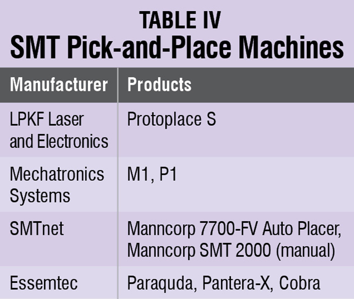
SMT pick and place
Once the PCBs are ready, you need to mount all the components and test the boards. Mounting of through-hole components is easy but SMD components require some skill and patience. So most people avoid doing it themselves and outsource the job, which costs money for making stencils and tooling, and time delay is always there.