Many engineers believe that all their design and testing requirements are met just by acquisition instruments like oscilloscopes and logic analysers. But a measurement setup is complete only when it has both acquisition and stimulus systems to complement each other. A signal generator pairs with the acquisition system to produce the most reliable test and measurement results.
A signal generator produces ideal waveforms that act as a stimulus for electronic measurement. Most circuits require some kind of signal to be fed at the input to study and test their output using anacquisition system comprising various instruments like oscilloscope, multimeter and logic analyser. The output makes sense only when you have an ideal and controlled input.
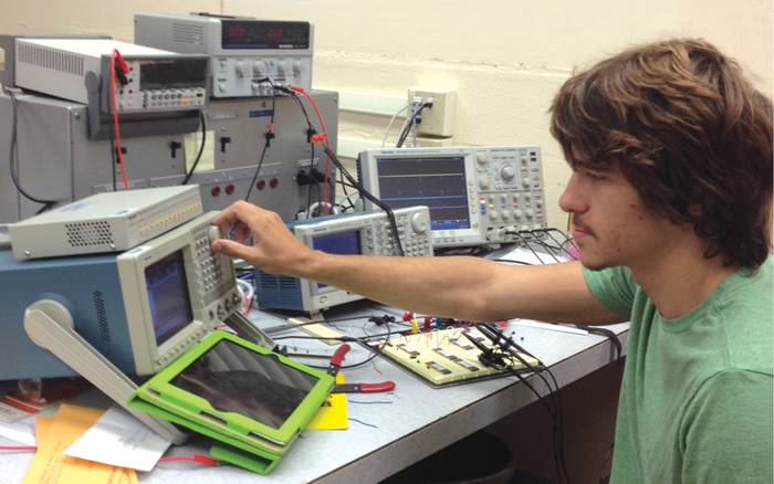
Signal generators can provide a variety of signals for testing, which can be controlled as per your requirement. The signal can be a sine wave, a digital pulse, a binary pattern, an analogue function or any other arbitrary waveform.
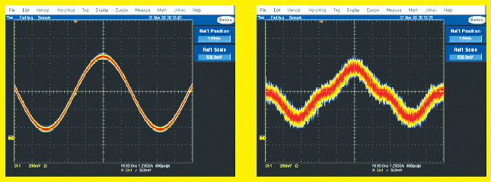
One of the greatest advantages of a signal generator is that it can even add a controlled distortion to the signal. This is highly useful to study the response of your circuit in presence of the distorted signal, as you can check how much your design can handle and accordingly decide the correct performances range (refer Fig. 1).
Why do you need one?
An acquisition system together with a stimulus system like signal generator makes up a complete testing solution that can feed a device with real-world signals and acquire and analyse the resulting outputs. You can measure the output at various test points easily but it makes sense only when you can control what goes in, and that you can only do when a signal generator is connected at the input.
Signal generators find various applications, all of which fall under three main categories: margin testing, verification and characterisation.
Margin testing. Engineers need to test their designs in order to ensure that these meet the design specifications across the full range of operation. This is known as margin testing. This is a design challenge that requires a complete setup with stimulus and acquisition systems. With such a system you vary all the input parameters using the stimulus and check the limits until which you get the acceptable output. This testing also identifies how much stress the device can take while still doing its reliable operation.
Characterisation. Every device comes with characterisation information provided by its manufacturer. Characterisation information is actually a behaviour summary of the device. This information becomes available after the device has undergone complete characterisation tests and the data has been analysed. The characterisation data gives the designer a better understanding of the device characteristics, to better judge the acceptability of the device to the application. Again, to run such tests, you need both a stimulus system like signal generator and an acquisition system like oscilloscope.
Verification. Verification is done to check whether a product meets a set of initial design requirements, specifications and regulations. In the development phase, verification procedures involve special tests on various modules. The results are modeled and the modeled results are reviewed or analysed to see whether the product complies with specifications. In the post-development phase, verification procedures involve regularly repeating tests devised specifically to ensure that the product continues to meet the initial design requirements, specifications and regulations as time progresses. A lot of development phase and post-development phase verification tests require a stimulus system like signal generator.
Type of signal generators
Signal generators are broadly divided into mixed-signal generators and logic sources, covering the whole range of signal-generation needs. Each of these types has its unique strengths that make it more or less suitable for specific applications.
Mixed-signal generators. These are designed to output waveforms with analogue characteristics. They produce various types of waveforms like sine, square/rectangular, sawtooth/triangular, step/pulse and various complex waves. These waveforms show the rounding and imperfections that are part of every real-world signal. Various parameters of these waveforms, such as amplitude, frequency, phase, DC offset and rise time/fall time, can be controlled in a mixed-signal generator. You can even create aberrations such as overshoot and add edge jitter, modulation and more.
Logic/digital sources. True digital sources, on the other hand, are designed to drive digital systems. Unlike mixed-signal generators, these cannot generate analogue waveforms like sine or triangular waves. Such signal generators output binary pulse streams. Their features are optimised for computer bus needs and similar applications.
Analogue or digital signal generator
Most signal generators today are based on digital technology. Many can fulfil analogue requirements as well. Arbitrary waveform generators (AWGs) and function generators are primarily designed for analogue and mixed-signal applications. These instruments use sampling techniques to build and modify waveforms of almost any imaginable shape.
What to look for while buying one
This is actually a difficult question, and the selection is completely driven by your specific needs. A detailed understanding of your requirements and specifications mentioned in the datasheet can help you select the right signal generator for you. A signal generator produces various waveforms and its specifications are directly related to waveform properties.
Usually, signal generators produce electrical waves that repeat in a controllable manner. Each full repetition of a wave is known as ‘period.’ A waveform is actually a graphic representation of the wave’s variation over time.
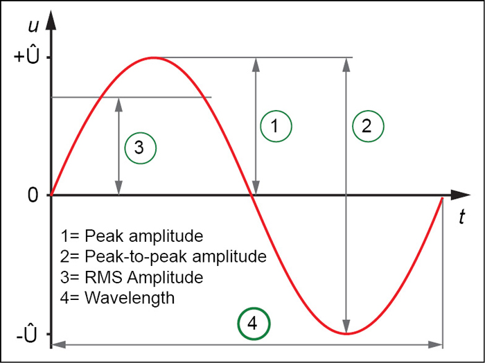
Amplitude. Amplitude is a measure of the voltage strength of the waveform. Amplitude of an AC waveform periodically changes with time. Signal generators allow you to set a voltage range over which the signal continuously fluctuates with a frequency selected by you. The various amplitudes of interest in a waveform are peak amplitude, peak-to-peak amplitude and RMS amplitude (peak amplitude/√2), as indicated in Fig. 2.
The amplitude specification for a common signal generator is 10-20V (open-circuit) peak-to-peak with 50 ohms impedance. 10V peak-to-peak sine wave has an RMS voltage of 10/√2, which implies that the generator will be able to deliver only 10/50 √2 amperes of RMS current at peak output. If you need more current or voltage than what is specified above, you will have to use a suitable amplifier or go for specialised function generators. So carefully check whether this specification suits your requirement.
For frequency response testing, amplitude flatness is also important. Amplitude flatness means that the fixed amplitude does not vary with the change in frequency.
Frequency. This is the rate at which full waveform cycles occur. Frequency is measured in Hertz (Hz), also known as cycles per second. It is inversely related to the wavelength (shown in Fig. 3 as point 4) of the waveform, which is a measure of the distance between two similar peaks on adjacent waves. The higher the frequency of the waveform, the shorter the time period.
The frequency specification of a signal generator is the highest sine wave frequency that the generator is capable of delivering. Many signal generators will have a lower maximum frequency specification for other waveforms. Here the minimum frequency that the generator can deliver is also important. For some applications, you will need very low frequencies. Signal generators with 1-micro-hertz resolution are readily available.
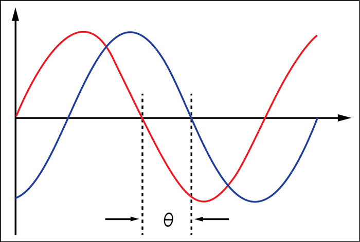
Phase. Phase in sinusoidal functions or in periodic waves has two different but closely related meanings. One is the initial angle of a sinusoidal function at its origin, and is sometimes called phase offset or phase difference. Another usage is the fraction of the wave cycle that has elapsed relative to the origin. Refer Fig. 3, where the phase difference between the red and blue waves is ‘θ.’
Phase shifts are common in electronics. The amplitude, frequency and phase characteristics of a waveform are the building blocks that a signal generator uses to optimise waveforms for almost any application. These are implemented as controlled variables in all the signal generators.
Rise and fall times. Rise and fall times, also known as edge transition times, are characteristics usually described for pulses and square waves. These are the measure of the time it takes for a signal edge to make a transition from one state to another. With the advancement in technology, these values have typically gone down to nanoseconds range.
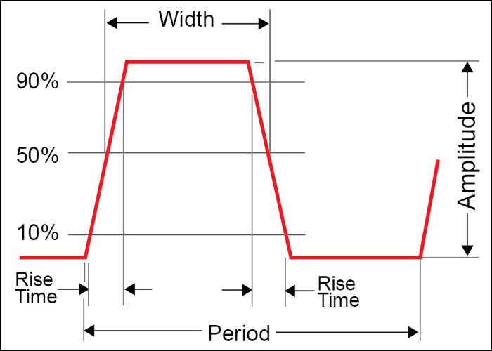
Both rise and fall times are measured between 10% and 90% points of the static voltage levels before and after the transition as shown in Fig. 4. You will need a functionality in the signal generator where you can vary the rise time and fall time independently for a waveform while testing applications such as an amplifier with asymmetrical slew rates. So look for a signal generator that supports this function.
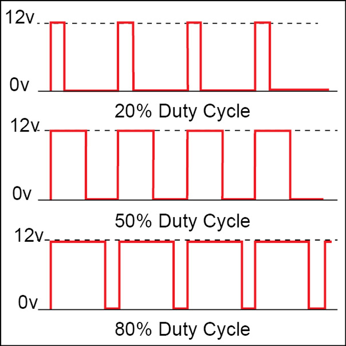
Pulse width. Pulse width is the time elapsed between the leading and trailing edges of a pulse. Pulse width measurement is expressed as the time between the 50 per cent amplitude points of the respective edges. This is an important variable function for a signal generator, which you will need while experimenting with servo motor, LED intensity, etc. Fig. 5 shows a signal with different duty cycles.
DC offset. Many signals have their amplitude variations centred above or below 0V reference. ‘Offset’ voltage is the voltage between circuit ground and the centre of the signal’s amplitude Variation. In effect, the offset voltage expresses the DC component of a signal containing both AC and DC values. This DC component needs to be handled carefully in most of the designs that require a stimulus system like signal generator in the design phase, which can vary this component in a controlled manner to test the implementation.
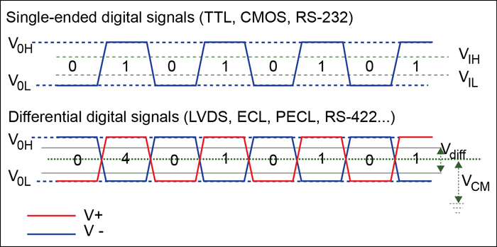
Differential signals. These are two complementary signals that have equal and opposite polarity with respect to ground. Fig. 6 shows the single-ended and differential signals. In differential signal, as the signal’s cycle proceeds one path becomes more positive, the other becomes more negative to the same degree. The differential architecture is good at rejecting crosstalk and noise and passing only the valid signal. Single-ended operation is a more common architecture, in which there is only one path plus ground. To design and test the systems that communicate via differential system, you need a signal generator that has this functionality.
Complex waveforms
The above-mentioned are only basic characteristics of the waveform and corresponding specifications of the signal generator. In operational electronic systems, waveforms rarely look like the examples explained above. Certain clock and carrier signals are pure, but most other waveforms will exhibit some unintended distortion. Some waveforms may even include elements of sine, squares, steps and pulses. To test, debug and design such real applications, more sophisticated stimulus signals are required than just simple waveforms. Do check whether the signal generator has these features because you are really going to need them.
Modulated signals. The most commonly required complex waveform is a modulated signal where the modulation parameters can be controlled. In modulated signals, amplitude, phase and/or frequency variations embed lower-frequency information into a carrier signal of higher frequency. The resulting signals may convey anything from speech to data to video. Such waveforms can be a challenge to reproduce, unless the signal generator is specifically designed for it.
Frequency sweep. If you want to check the frequency response of your device, you need frequency sweep function in your signal generator. It generates a sine wave whose frequency changes over time. This frequency change occurs linearly in Hz/second or logarithmically. Some signal generators even provide sweep sequencing facility, where start, stop, hold frequency and associated time can be defined. Some signal generators also provide a trigger signal synchronously to the sweep to control an oscilloscope that measures the output response of the device.
Digital patterns. A digital pattern consists of multiple synchronised pulse streams that make up ‘words’ of data that may be 8, 12, 16 or more bits wide. The most common signal formats that also come under complex waveforms category are:
1. Non-return-to-zero
2. Delayed non-return-to-zero
3. Return-to-zero
4. Return-to-one
Only specialised signal generators support these waveforms.
Performance specifications
Now after discussing the waveform- related specifications, given below are some performance-related specifications of a signal generator. These specifications have to be checked carefully to select the best signal generator in the range.
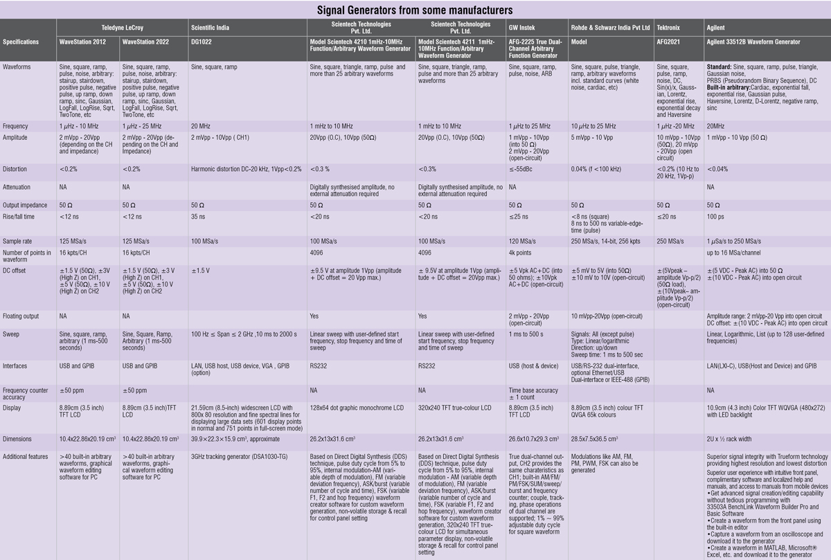
Memory depth. Also known as record length, it determines the maximum number of samples that can be stored. Memory depth plays an important role in signal fidelity at many frequencies because it determines how many points of data can be stored to define a waveform. Particularly in the case of complex waveforms, memory depth is critical to reproducing signal details accurately. High-performance mixed-signal generators offer large memory depth and high sample rates. These instruments can store and reproduce complex waveforms such as pseudo-random bitstreams.
Sample rate. The Nyquist Sampling Theorem states that the sampling frequency must be more than twice the highest spectral frequency component of the generated signal to ensure accurate signal reproduction. For example, to generate a 2MHz sinewave signal, it is necessary to produce sample points at a frequency of more than 4 megasamples per second (MSa/s). Although the theorem is usually cited for digital oscilloscopes, it works equally well for signal generators. The stored waveform must have enough points so that the signal can be reproduced reliably. Go for a signal generator with the highest available sample rate specification.
Bandwidth. The analogue bandwidth of the output circuitry should be large enough to support the highest frequency signal that the signal generator can produce. This bandwidth is independent of the sample rate. If there is not enough bandwidth, the signal characteristics may degrade.
Horizontal and vertical resolution. Horizontal resolution is the smallest time increment that can be used to create a waveform. It is actually inversely proportional to the sampling frequency. By this definition, the timing resolution of a signal generator with maximum clock rate of 20 MHz would be 50 nanoseconds. On the other hand, vertical resolution of the DAC defines the amplitude accuracy and distortion of the reproduced waveform. A DAC with inadequate resolution contributes to quantisation errors, causing imperfect waveform generation.
Output channels. Many applications require more than one output channel from the signal generator. Some signal generators can deliver up to four independent channels with full bandwidth. Others offer up to two analogue outputs, supplemented by some high-speed digital outputs for mixed-signal testing. Check in advance your requirement of the number of outputs because this will considerably add to the overall price.
The author is a technical editor at EFY


