No manufacturing process is perfect and there is always a percentage of boards with defects. These boards need to be repaired or discarded to ensure the quality of the end product. Various inspection processes are designed to efficiently find out these defective boards and segregate them from the good ones. Most defects, such as misaligned components, wrong orientation, solder bridging, open connection, improper soldering and physical damage can be easily detected by visual inspection. There are certain defect types that can only be discovered by more sophisticated techniques such as X-ray imaging. But visual inspection remains the primary means of finding defects in circuit assemblies and correcting them before they reach later stages of test.
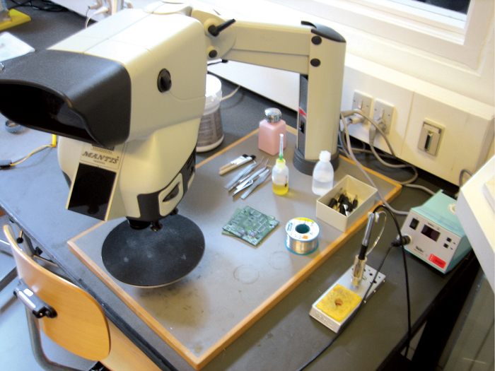
Visual inspection standard
IPC-A-610E standard, which is a collection of visual quality acceptability requirements for electronic assemblies, also indicates the need for magnification aids and acceptable parameters. Reproduced below is the ‘Magnification Aids’ section from IPC-A-610E standard:
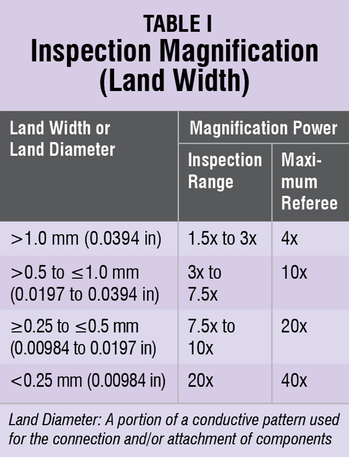
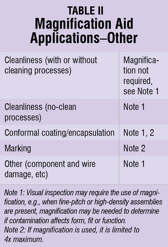
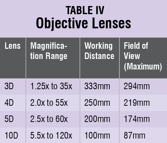 1.9 Magnification Aids: For visual inspection, some individual specifications may call for magnification aids for examining printed board assemblies.
The tolerance for magnification aids is ±15% of the selected magnification power. Magnification aids, if used for inspection, shall be appropriate with the item being inspected. Unless magnification requirements are otherwise specified by contractual documentation, the magnifications in Table I and Table II are determined by the item being inspected.
Referee conditions are used to verify product rejected at the inspection magnification power. For assemblies with mixed land widths, the greater magnification may be used for the entire assembly.
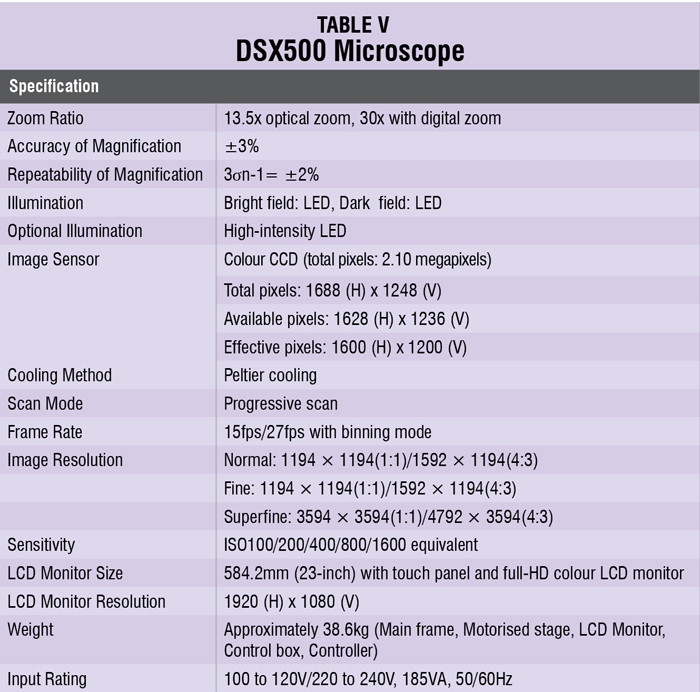
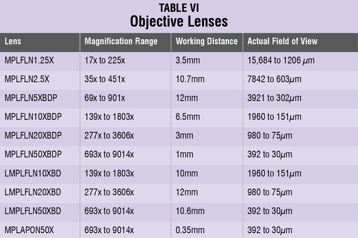
Illumination
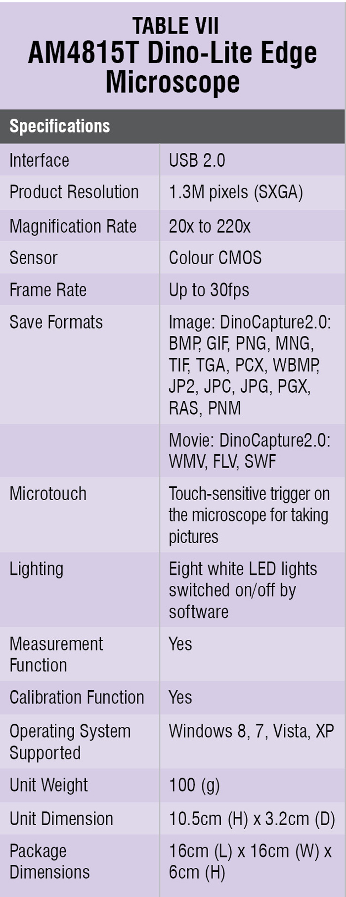 The human eye only sees the information carried by reflected light. Therefore illumination of the object is as important as magnifying it. The IPC-A-610E standard does not give much detail about the illumination. Reproduced below is the ‘lighting’ section from the standard:
1.10 Lighting: Lighting shall be adequate for the item being inspected.
Illumination at the surface of workstations should be at least 1000 lm/m2 (approximately 93-feet candles). Light sources should be selected to prevent shadows.
Note: In selecting a light source, the colour temperature of the light is an important consideration. Light ranges from 3000 to 5000°K enable users to distinguish various printed circuit assembly features and contaminates with increased clarity.
There are several types of microscope illumination. The basic type mounts on the microscope itself and has a hood over a circular fluorescent bulb. The circular shape distributes illumination evenly. Fluorescent lamps have long been used for such applications but the greenish spectrum of light emitted by them, besides flickering, shadows and humming caused by the ballast, annoy operators and cause eye fatigue. With the advent of solid-state technology and advances in fluorescent light science, these lamps now provide higher intensities of cool, white light across the entire spectrum without flickering and shadows. Even dimming of light has now become possible.
Illumination through fibre-optic cable is done by generating light through an external power unit and supplying it via a flexible, metal-sheathed fibre-optic cable. The intensity can be adjusted at the generator end, giving the operator a high degree of control over the amount and intensity of light distributed on the inspection area. The highest level of optical inspection magnification and clarity is provided by these microscopes and almost all microscopes in use today are of this type.
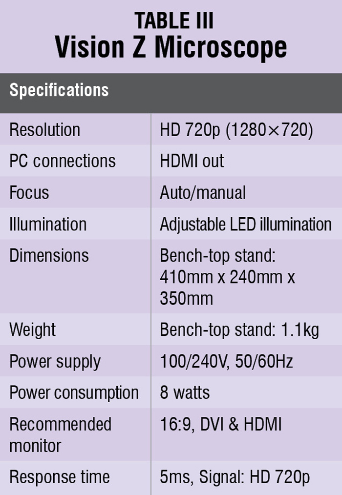
High-magnification CCD cameras are also used in optical inspection, where the image is projected onto a colour monitor screen. Their advantage is that multiple individuals can view the same image simultaneously. It is also easy to capture digitised images for transmission over the Internet, or for training videos, etc. Either way, proper lighting is critical.
Illumination colour is very critical for some applications, especially for those using machine vision. The special types of coloured lighting used include yellow bulbs for inspecting photo-resist, and ultraviolet light for inspecting the conformal coatings, plating voids and certain other flaws. The wavelength of light used here is not in the range of harmful UV. Overall, the percentage of speciality coloured lighting used in inspection is quite small, and is specific to certain limited applications.
ESD safety
The issue of electrostatic discharge (ESD) safety in illuminated magnification is an important one. The illuminated magnifier used in the microscope is a powerful source of ESD, suspended right above the workpiece. The manufacturers want to protect their products from ESD and ground everything in contact with the operator and the bench-top. The best way to protect products from potential ESD damage is to ensure that the magnifier used has quality metal parts, or ESD-safe plastic parts.
Diopter
Diopter is a unit of measurement of optical power of a lens, which is equal to the reciprocal of the focal length in metres. For example, a typical 127mm (5-inch) diameter lens may be rated at 3-diopter, with a magnification of l.75x. The same lens in 5-diopter would have a 2.25x magnification.
A thorough knowledge of available technology for visual inspection, as well as the specific needs of your inspection application, can help you choose the most appropriate inspection equipment for the job.
Minimising operator fatigue—eye fatigue or otherwise—is essential to maintain good inspection procedures, practices and operator effectiveness. Optical inspection equipment is not as simple as it may seem, and ongoing technological innovations continue to improve both the quality and functionality of visual inspection equipment.


