


Developed at the University of California and first released in 1972, Automatic Integrated Circuit Modeling Spice, or AIM-Spice, uses SPICE format for describing analogue circuits. Unlike SPICE, which uses control records, AIM-Spice uses point-and-click type controls. This article focuses on AIM-Spice.
Abhishek Mutha
SPICE is a well-known, widely documented and standard analogue simulator in the electronics industry. A general-purpose analogue simulator, SPICE can handle complex non-linear circuits and also contains models for most of the circuit elements. Calculation of DC operating points, transient and distortion analyses, locating poles and zeros for different kinds of transfer functions, finding the small signal frequency response and small signal transfer functions, and performing Fourier functions are a few functionalities of the simulator.
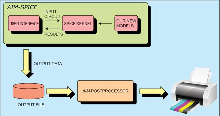
Compatible with Microsoft Windows and Linux operating systems, AIM-Spice is a new version of SPICE. The AIM-Spice simulation package consists of two main applications—AIM-Spice itself and a graphic postprocessor called AIM-Postprocessor.
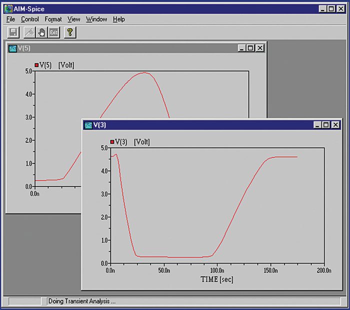
The development of AIM-Spice was motivated by the need for a new set of advanced device models for circuit simulation and a more user-friendly interface. For Windows, AIM-Spice is capable of displaying graphically the results of a simulation in progress—a feature that allows the user to terminate a run based on an instant information on intermediate simulation results.

Features
Running on Microsoft Windows and Linux operating systems, AIM-Spice uses the Berkeley SPICE version 3.E1 as the kernel. It displays the simulation results in progress by plotting graphically circuit variables during a run. It includes advanced new models for a number of semiconductor devices.
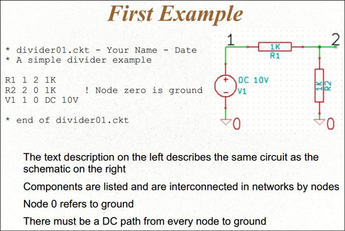
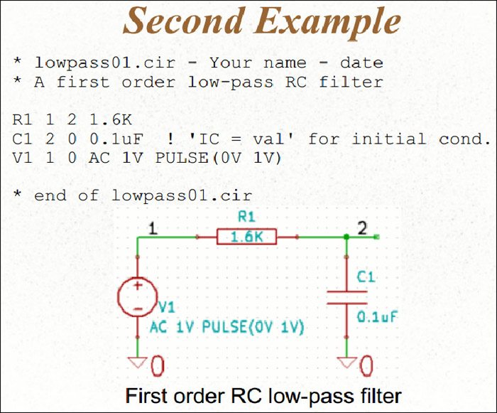
 AIM-Spice is considered as a simple and effective simulation tool for use with analogue circuits. It uses traditional SPICE-like circuit descriptions but without control records. The simulation control uses simple point-and-click approach. The AIM-Spice help menu is very comprehensive. AIM-Spice toolbars in help section explain all of the icons.
Simulation control
In AIM-Spice for Windows the operator has complete control during a simulation. Before it starts, circuit variables that are to be monitored during the run are selected. AIM-Spice software graphically displays the progress of these variables during the simulation.
Circuit analysis with AIM-Spice
There are different types of analyses in AIM-Spice:
1. Operating point analysis. This analysis simply calculates the DC operating point. No parameters are required.
2. DC transfer curve analysis. In this analysis, one or two sources—a voltage or a current source—are swept over a user-defined interval. DC operating point of the circuit is calculated for each value of the source(s). DC transfer curve analysis is useful in finding the logic swing of logic gates or I-V characteristics of a transistor for example.
3. AC small signal analysis. This analysis calculates the frequency response of a circuit by linearising circuit equations around the operating point.
4. Transient analysis. The time domain response of a circuit is calculated from t=0 to a user-defined upper time limit. This analysis has two optional parameters. The first one specifies that the generation of output starts at a value different from zero. The second optional parameter sets an upper limit on the time steps used by AIM-Spice.
5. Pole-zero analysis. AIM-Spice is able to locate poles and zeroes in an AC small signal transfer function. First, DC operating point is calculated, and then the circuit is linearised around the operating point. The resulting circuit is used to locate poles and zeroes.
6. Transfer function analysis. This analysis computes the DC small signal value of the transfer function, input resistance and output resistance.
7. Noise analysis. Noise analysis portion of AIM-Spice computes device-generated noise for the given circuit. When provided with an input source and an output port, it calculates noise contributions of each device and each noise generator within the device to the output port voltage. It also calculates input noise to the circuit, equivalent to output noise referred to the specific input source. This is done for every frequency point in a specified range.
8. Distortion analysis. Small signal distortion analysis part of AIM-Spice calculates steady-state harmonic and inter-modulation products for small signal input magnitudes. If signals of a single frequency are given as input to the circuit, values of the second and third harmonics are computed. If there exist input signals of two frequencies, the analysis finds out values of circuit variables at sum and difference of the input.
All analyses are made available as commands from the Analysis menu. All analysis commands, except for the DC operating point analysis, require additional control parameters to be specified. However, before choosing one of the commands in the Analysis menu, one should decide which circuit to analyse and make the corresponding circuit window the active window.
New semiconductor device models
For the following semiconductor devices, new advanced models are implemented in AIM-Spice:
1. Heterostructure diode
2. Heterojunction bipolar transistor
3. MOSFETs. The following MOSFET models are included:
Level 1, 2, 3 and 6 from Berkeley
- BSIM1
- BSIM2
- BSIM3v2
- BSIM3v3.1
- BSIM3v3.2
- BSIM3 SOI
- BSIM4 versions 1, 2, 2.1, 3 up to 6
4. GaAs MESFETs and HFETs
5. Amorphous silicon thin-film transistors (a-Si TFTs)
6. Polysilicon thin-film transistors (poly-Si TFTs)
All the FET models are based on versions of the unified charge control model, which describes the channel charge in field-effect transistors (FETs) in the above and below threshold regimes, using one analytical expression.
Extensions to Berkely SPICE
1. Temperature sweep analysis
2. Support for libraries
3. Libraries consisting of thousands of devices
4. Support for parameters in the netlist
5. Support for parameters in sub-circuit calls
6. Polynomial dependent sources (POLY sources)
7. Global nodes
8. BSIM3 versions 2 and 3
9. BSIM4 versions 1, 2, 2.1, 3 and 4
10. Support for extended commands:
- .connect
- .defwave
- .global
- .lib
- .param
- .plot
11. Enhanced commenting features (comment blocks and comments within continuation lines)
AIM-Postprocessor
As mentioned earlier, a graphic postprocessor is included in the AIM-Spice simulator package. Like AIM-Spice, this application also runs under the Microsoft Windows environment.
Although AIM-Spice has facilities to plot circuit variables graphically, the postprocessor has a much more powerful plotting engine including the following features:
1. Creating hard copies and plotting of derivatives, integrals, sums and differences, and mathematical functions of circuit variables
2. FFT (fast Fourier transform)
3. Calculation of differences between variables and cursors to select numerical values
4. Import of experimental data
5. Hard copies
Download the latest version of the software: click here
The author is a tech correspondent at EFY Bengaluru
