


The best way to learn electronics is to see what is really happening in the circuit designed. Electronics circuit design today has become very convenient and interesting with design simulation tools. CircuitMod is one such simulation tool that can be used by beginners and professionals alike for their electronics projects. It delivers much more than conventional simulation software.
What CircuitMod can do
An interesting feature of CircuitMod is that instead of representing the output values of a circuit after simulating it in the backend, the software allows users to digitally see how the circuit performs during simulation. The open source software allows users to adjust the simulation speed while taking readings. One can run the default circuit pre-built in the software or modify it with new or existing components.
The easily-understandable interface comes with a black screen as the main simulation area. This is where the circuit with all its components is digitally displayed. The circuit represented by dotted lines is wiring.

Voltage characteristic in different parts of the circuit is distinguished by specific colours. For instance, negative voltage is symbolised by red and positive voltage by green. Grounded circuits are shown as grey. Current flowing through the dotted lines is represented with yellow.
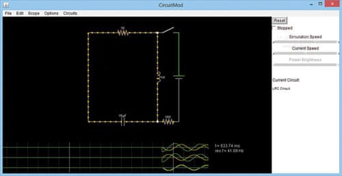
The bottom of the simulation screen holds three graphs, plotting real-time voltage versus current values of different components/circuit sections. The values change depending on the value actually flowing through the circuit.
The interface is quite interactive. Hovering the mouse over the circuit components pops up descriptions about the components. Modifications to the components can be done by right-clicking the desired component. A small window pops up, where updated values can be inserted.
The right side of the screen holds control bars denoting the simulation speed, current speed and power readings. It also contains the reset button. The top side contains the toolbar with menus like File, Edit, Scope, Options, Circuit and Help.
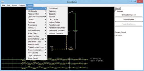
To start a new project, click ‘Circuit.’ A dropdown opens all the pre-installed circuits in CircuitMod. Some examples include basic circuits, AC circuits, passive filtering circuits, active filtering, phase-locked loops and more.
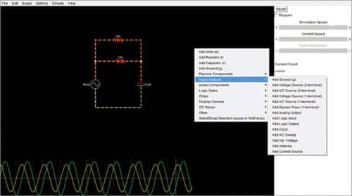
If you want to make a circuit of your own, choose Blank Circuit. To add components to the blank workspace, right-click the black space and choose components.
Components can be rearranged by simple drag-and-drop. Reset button in the top right panel, when clicked, starts the circuit function.
Data from the circuit can be extracted. While the circuit is running, go to File in the top toolbar and select Export Text. Data will get saved in Notepad.
The full package
CircuitMod Version 2.7 comes with expanded support and features. It extends the original Falstad’s Java Circuit Simulator with newer circuits and elements like PIC programming, LED matrix, transistor-transistor-logic (TTL) circuits and complementary metal-oxide semiconductor (CMOS) chip circuits apart from analogue circuits. JFETs, MOSFETs, op-amps, oscillators and transmission lines are also available.
Basic circuit components include resistors, inductors, capacitors, diodes and voltage dividers. A popularly used circuit category is AC Circuits, which evaluates the behaviour of components under alternating current. Correlation to frequencies makes practical analysis of concepts like resonance and impedance much simpler.
Passive circuits are an essential part of the software. Elements like filter, crossover circuits, transformer and differentiator make a strong inventory for designing a complete passive circuit. With coloured voltage representation and real-time current and voltage data display, power factor analysis becomes easier.
To sum up
CircuitMod is a handy tool for beginners to understand how a circuit actually behaves in real life. It is equally useful for professionals to evaluate the working characteristics of the circuit they designed. Unlike other simulation tools, CircuitMod runs everything in the open. It can run on Windows, Linux and Mac OS X.
