


FidoCADJ is a Java-based multi-platform editor for more than just electronics. It offers a very clean and intuitive environment to help users design their electronics with ease. FidoCADJ is not a simulator, but it offers an agile and effective environment for hobbyists. While there is no netlist concept, it comes with a library that includes electrical symbols and footprints (traditional and SMD) to assist you in your drawings.
FidoCADJ generates electronic circuit outputs with a very compact textual description in various file formats. This makes it very easy to include these drawings in text messages and exchange your sketches in forums and newsgroup discussions.

Some regard FidoCADJ as a Java-based modification of FidoCAD software, which can only be run on Windows. However, it is actually a completely re-written program that offers full compatibility with FidoCAD files, and allows for showing and modifying a file using FidoCAD format. It is not just an adaptation or extension for FidoCAD.
If you are familiar with FidoCAD, getting used to FidoCadJ will not be a problem. In fact, many commands and procedures are quite similar to the original application including some extensions as well.
Compact and efficient
 A major advantage of working with FidoCADJ is its simple text format. With no header description required, a simple coordinate system for drawing and various drawing elements, it offers a compact and efficient storage format for the drawings. From the latest version included in this DVD, it uses only the UTF-8 encoding on all formats.
Unlike other CAD tools and its predecessor FidoCAD, FidoCadJ includes an interpreter that can recognise and correctly interpret any file with or without standard header. Moreover, it can also correctly interpret commands containing text, as long as the number of incorrect lines does not exceed a value set internally in the program (approx. 100). This ensures a fast and efficient functionality, wasting no time, for example, in trying to open a very large binary file.
A simple coordinates system in FidoCADJ identifies a very large area only by whole and positive coordinates. The fixed unit length of in x and y axes at 127μm allows to obtain a good resolution (about 200 dots per inch) for even the smallest SMD packages, without being too fine for everyday use.
Intuitive environment
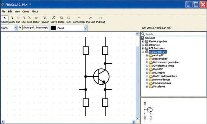
FidoCADJ offers graphical flexibility and several intuitive drawing features. In the toolbar situated on the top of the window, you will find the most used and common features for creating and editing a drawing. Some of the features and functionalities in FidoCADJ, which account for ease of use of this intuitive tool, are discussed below.
The vacuum-tube radios and switches of old times inspire the elements of ease of use in this tool. When you press a button, it remains in that position until another function from the toolbar is selected. So you don’t need to press again and again for the same element in your circuit. Also, you can easily edit or modify the parameters like coordinates or rotation of any drawing element just by double-clicking on it in selection mode.
Intuitive ruler. Drawing a PCB requires measuring distances in the working area. This tool offers an intuitive ruler feature that allows you to easily check any track width, the clearance between two tracks or the total size of a card. You can just right click and drag to open a ruler in green for your help.
Keyboard shortcuts. From selecting multiple graphic elements to drawing a PCB pad, there are various drawing commands available in FidoCADJ. These allow you to rapidly select various features that let you design faster (as shown in the table), without having to manipulate your mouse.
Flexible graphics. It also offers three different zoom settings for graphical flexibility with the buttons like Fit, Show Grid and Snap to Grid. You can automatically select the most suitable zoom settings in order to show the whole drawing on the screen by pressing Fit button. Show Grid makes it easy to toggle between visible and invisible grids. Finally, the elements added will stick to the nearest step of the grid utilising the Snap to Grid button. (Note: To carefully align various elements, Alt key should be kept pressed while using the other cursor keys.)
 Partial customisation of command bar. FidoCADJ also allows you to partially customise the command bar. In particular, you can either choose to see the icon on each button or both the icon and its text description. These two selectable formats for the icons can be changed from the menu File → Options. Any change in the settings will be applied at the restart of the application.
Easy search and navigation. The libraries include all the standard symbols used in electrical schematics and a wide selection of footprints for drawing PCBs. A quick search text field allows for the quick searching inside the included libraries and the results appear in the form of a tree, allowing you to easily navigate through by typing up and down arrow keys.
