Regular readers of this section must have seen many circuit simulators by now, but how many of these actually allow us to modify the circuit at the simulation stage? Well, here we have one such simulator, IRSIM. This tool allows us to modify the circuit under simulation and re-simulate it using IRSIM. IRSIM is available for both Linux and Windows operating systems (OSes).
 IRSIM, not the Invisionix Systems’ portable instant messenger you get when you Google the term, is an interactive and incremental logic-level simulator used for metal oxide semiconductor (MOS) transistor based digital circuits. Pronounced as eye-are-sim, this tool is not an infra-red simulator, but is always referred to as a switch-level simulator.
Why switch-level simulator
The open source software IRSIM has the ability to simulate in two modes: switch and linea r. During switch mode, it initialises and determines the functionality of a MOS network, whereas in case of linear mode, it determines the number of times the gate delays and the circuit transition occurs.

An interesting point to note is that although it has the ability to work in two different modes, we still relate it to only one mode. The reason is that, IRSIM models the circuits at transistor level where these transistors are modelled as switches. At this point, most analogue and higher order properties of the devices into consideration are ignored and these are treated as ideal on/off connections.
A simulator but not an editor
We are all aware of the importance of a digital circuit simulator and that it needs a netlist to work. A netlist is a circuit schematic with components and connections created by a circuit editor or circuit design tool. Now, do not confuse IRSIM with a design tool or an editor, as it can simulate but cannot create a netlist. Although it is an independent tool, it easily accepts a netlist from other tools.
Circuit behaviour and IRSIM
IRSIM being a switch-level simulator works on three important aspects of the behaviour of a digital circuit, namely, transistor state, logic value and transition events.
A transistor state is a linear model state, where each switch has two states: on and off. This linear model helps IRSIM reflect the differences between the different types of transistors, rise and fall times of the gate and different fabrication processes very accurately.
![]()
On the other hand, the logic value behaviour of the circuit allows IRSIM to treat voltages in a circuit as three different values, that is, high (h,1), low (l,0) and indeterminate (unknown or x). This way, IRSIM does not have to bother about the actual voltage that is powering the circuit. The linear model works with these voltage values and helps compute the generation of a normalised (high) voltage.
The above two aspects help us identify the simplified modelling of a circuit using IRSIM. However, on account of transition events, IRSIM treats a circuit as a cascade of events. This makes IRSIM an event-driven simulator. Let us understand how.
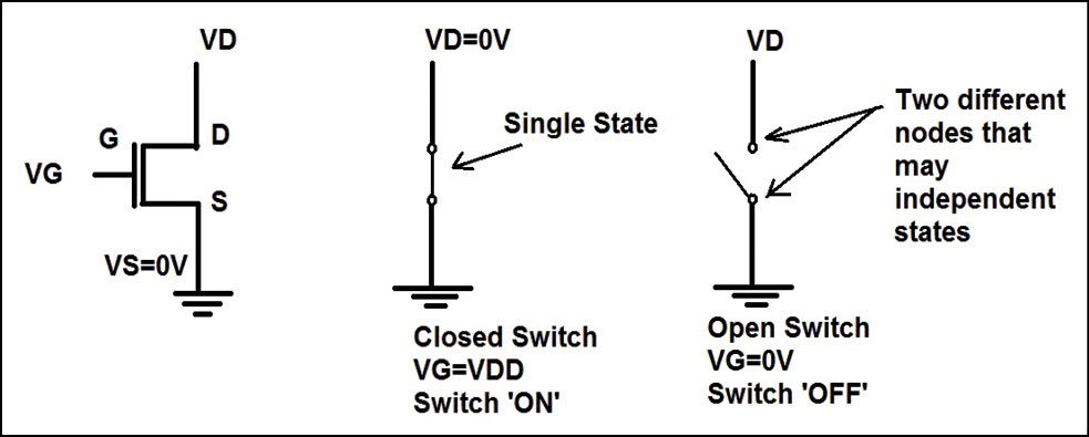
All switch-model transistors have a source-to-drain path and a controlling gate that is either on or off. On occasion when the transistor switch is on, source-to-drain nodes are combined to form a single path that can have only one state.
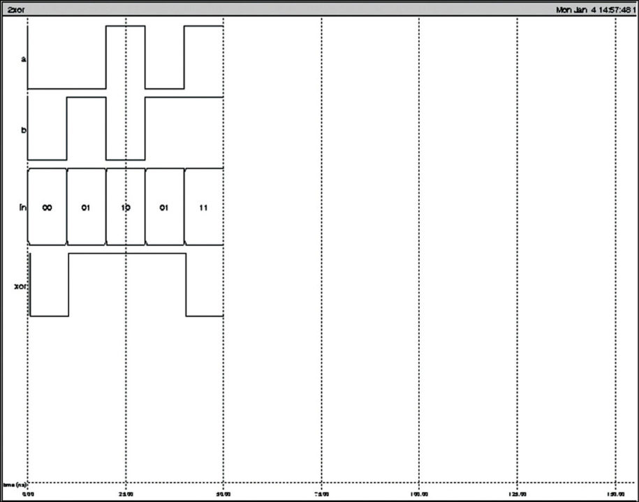
Whereas, when the transistor switch is off, source-to-drain nodes belong to two different paths and may even have independent states, as shown in Fig. 3. This change in state of a gate is considered to be an event that causes IRSIM to re-evaluate the paths between the source and the drain based on the event.
A completely different simulation experience
Each tool has its own advantage that can tempt you to use it, provided the advantages are known and easy to understand.
Modifies simulation and re-simulates incrementally. IRSIM allows modification and re-simulation of corrected errors along with verification of circuit operation. It also maintains a history of all circuit activity during simulation, depending upon which only the circuit that deviates from the history is re-simulated. The overall time taken for this is proportional to the size of the modification and not to the size of the entire circuit; so the simulation is fast.