


According to the IP-XACT format, each object should be given a unique identifier defined by the fields’ vendor, library, name and version. In this example, we are using the naming
convention specified in Set Vendor to ‘Altera.’ Use ‘ip.hwp.communication’ for the Library field, ‘avalon_bus’ for the Name field, and ‘1.0’ for the Version field. Click OK to create the new bus.
Normally, after creating the bus, we define the bus signals in the appeared ‘avalon (1.0) [bus]’ tab. But this example focuses on creating hierarchical system and documentation features of Kactus2. So now we can create buses without any signals; hence, close that tab.
Creating a hardware component
This is similar to creating a new bus. Go to File→New. Select HW Component from the left hand menu of the pop-up window. The Product Hierarchy option lets you choose which type of component you are specifying; select IP from the pull down menu. The Firmness option gives information on how the component can be modified; select Template from this pull-down menu.

Fill in the VNVL fields with your G (group 3 would use G03, etc…), ‘ip.hwp.cpu,’ ‘nios2,’ and ‘1.0’ as given in Fig. 3. Create the ‘hardware component’ by pressing OK.
After creating the component, a new tab opens which is filled with information about the component. In the given example, the only bits of information to be filled for each component are the bus interfaces and CPU details.
Adding interfaces to components
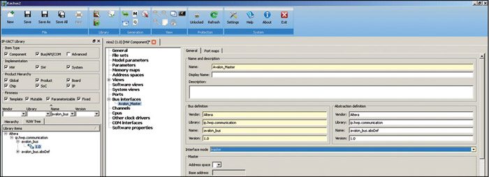
We only need ‘avalon_bus’ for the Nios2 processor component. From the list shown on the Nios2 tab, select Bus Interfaces. Double click on the empty list space to create a new bus interface and type ‘Avalon_Master’ in the name field. You can also give a display name and description to this interface.
It is to be noted that you are not able to edit the Bus Definition column in the Bus Interfaces list. Open the bus interface by going to the tree view: Bus Interfaces→Avalon Master and double click on it. In order to tie the bus interface to the actual bus, we should fill in the Bus definition and Abstraction definition fields. This is done by using the drag and drop method from the hierarchy pane. Expand ‘avalon_bus’ from the hierarchy pane to show the Abstraction definition for this bus. The resulting bus interface definition would look like what’s shown in Fig. 4.
The next thing to specify is the interfacing mode for the bus interface. The most typical setting is either master or slave mode, and can be found from the Interface mode section. Here the Nios2 processor acts as master on the ‘avalon_bus.’ so select Master from the pull-down menu shown in ‘Error! Reference source not found.’ You can add more bus interfaces to it using the same basic principle.
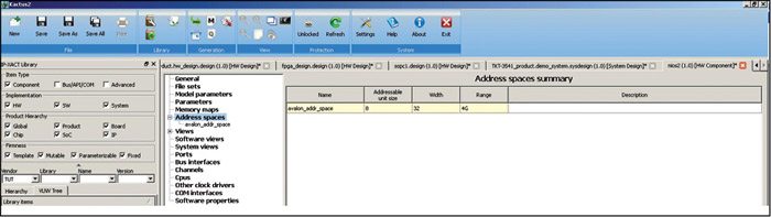
We can identify the created component as a CPU component by adding address space to it. Select Address spaces from the list given on the left. Add a new address space to the address space summary list, and fill the cells as shown in Fig. 5. Now the component can be identified as a programmable one. Select CPUs, double click the empty area to add a new line to the list, give a name to it, select the address space reference to the created ‘avalon_addr_space’ and save the component.
Creating channel components
This component is pre-given in the exercise work library.
To make HIBI bus, we need to make a special component that represents the HIBI interconnection network. Create normal components with product hierarchy IP, and fill the VLNV fields as G, ‘ip.hwp.communication,’ ’hibi,’ and ‘draft.’ The following bus interfaces need to be added to the component:
1. Slave interface to system_clk_bus
2. Slave interface to rst_n_bus
3. Mirrored master interface to hibi_bus
4. Second mirrored master interface to hibi_bus
5. Third mirrored master interface to hibi_bus
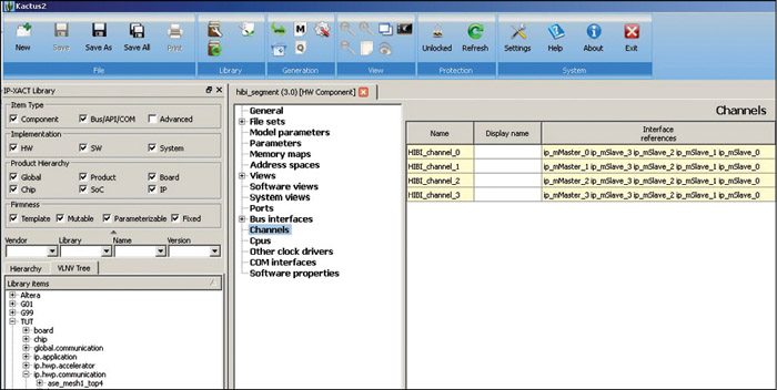
On creating the required bus interfaces, select Channels from the list on the Nios2 tab, and press the ‘+’ button to create a new channel. Enter ‘hibi_Channel’ in the Name field. Double click on the Bus interference reference field and select all hibi_bus bus interfaces to be added to the channel. Now the window will look like what’s shown in Fig. 6.
Creating a hierarchical design
When all components and buses are made, we can proceed to the actual hierarchical system design. Go to File→New, select HW design from the pop-up, select SoC from the Product Hierarchy and Mutable from the Firmness pull-down menu. Fill in the VNLV tuple and click on OK to create a new hardware design.
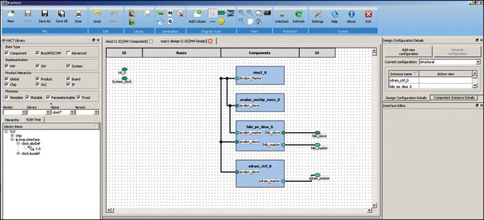
Drag and drop different components to the design using the Hierarchy or VLNV Tree menu on the left. Tools are provided in the Diagram Tools in the top pane for creating ports and connecting components together with buses.
Some of the basics of Kactus2 have been covered here. By successfully completing the exercise work systems with Kactus2, you can use available IP-XACT components, create your own components, or use draft components.
Download now: click here
The author is a tech correspondent at EFY Bengaluru
