A breadboard is like staple food to every electronics enthusiast. This is the first thing you would turn to when there is a circuit to design. Converting the lines and curves into signals on the oscilloscope or figures on a digital display is what you as a designer would put your entire efforts into.
Everything works and then comes the most important piece—the board. It is the board that decides the fate of the circuit. But what if you are working with perf and strip boards? How do you go about laying out the circuit? PerfDesign is here to help you!

PerfDesign is a tool for quickly designing or sketching projects on perf and strip boards. Get your Windows laptop, fire up your system and install the package. In a matter of minutes, you will be good to go. But do you even need software to create a design on a simple perf board?
Why PerfDesign
When I worked on my first big project, I started off by creating a working prototype on a breadboard. My professor then told me to replicate the same on a general-purpose PCB—a plain flat board with rows and columns of holes. Translating to the new board, which I later got to know was indeed the perf board, resulted in more stability, lesser noise, an easy-to-handle board and basically better results.
I remember sitting down with a pencil and paper in hand, tracing out graph-like checked squares and trying to put down components on it to scale. I began by drawing a resistor as big as the original one at hand, counting the number of dots before placing the second resistor to make space for node B, and so it went.

After many a drawing and erasing, I managed to get my final circuit to look the way I wanted—component placement, solder, wires and spacing between everything, all taken care of. I wanted the circuit to be neat, after all!
The main problem with designing like this, apart from the sheer number of iterations, is for a layout that involves a lot of cross-crossing; the drawing needs to be that much more accurate!
How much more difficult would it be for creating paths for connecting the ports for I/O devices, or maybe revamping the circuit to accommodate a new design? Enter, PerfDesign!
The crosschecks
 PerfDesign is a software that lets you design perf or strip board layouts. This is an easy-to-use tool that helps you quickly put together a layout on a custom PCB. Begin by laying out the components, make way for nodes by moving everything around and finish by connecting the design via traces. I find it easier to use and debug by keeping the layout as close to the schematic as possible.
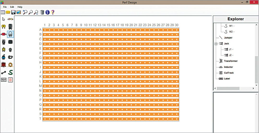
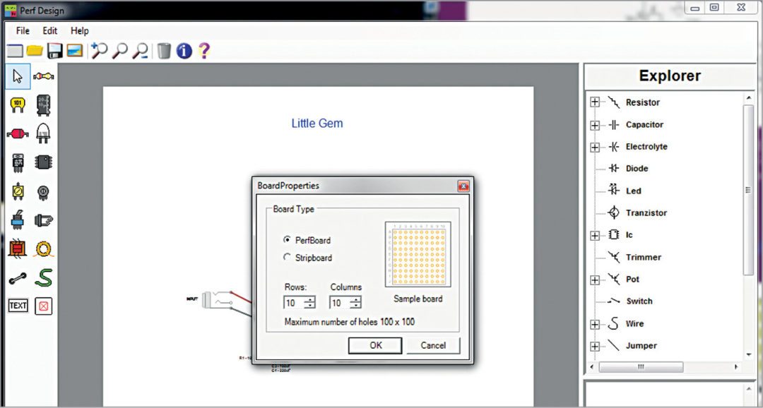
When you start a new project on PerfDesign, you either choose the perf board or go with the strip board model. How do you choose, though?
The perf board is a set of holes arranged in neat rows and columns. The strip board is exactly the same, except that the holes along each row are connected via copper traces. The former lets you design everything just the way you want, while the latter is easier to work on if all you want to do is replicate the design on the breadboard. You can create boards of different sizes, up to 100×100 holes.
Pick and place, create and edit, on a single screen
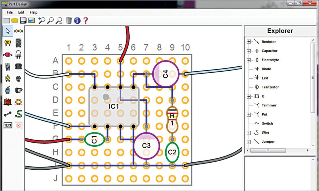
The graphical user interface (GUI) of PerfDesign is neat and simple, designed for easy usage. Resistor, diode, transistor, capacitor, integrated circuit, trimmer, LED, potentiometer, switch and jumper—all design components including connectors, wires and track cutters are placed right at one end of the screen. At the other end, there is Explorer window that lets you play with different combinations of values and fine-tune circuits to achieve desired results, instead of changing, say, the resistor each time.
As you add each component, you can choose properties to have a basic design to begin with. The board is created right at the centre of the screen. Just below the board, there is a component overview area that lists out all components used (parts list) in the design, along with their details.
Working your way around the board is very easy. Just a few clicks of the mouse lets you add new components, drag these around to create the intended design, resize these, change properties and basically create, re-create or tune the board to achieve perfection. You can also zoom in to ensure proper connectivity, or pan the entire design to one end in order to re-structure the board. If the board is too huge and complicated, use Component Explorer menu to get a compact view, with components listed, sorted by type and name.
The board is designed, what next
Overwhelmed by the number of easy-to-design PCB tools, we rarely use perf or strip boards anymore. But the fact remains that such boards are probably the best choices for quick prototypes and, if well done, long lasting ones, too. When compared to printed boards, these are certainly easier to work with and, more importantly, to debug. Yes, you might end up putting the capacitor leads into wrong holes, or solder something wrong, but redoing it will not take too much effort.
You have created your design and laid it out neatly on the perf or strip board. Now, all you need to do is copy the same on the real board. This is a cheap solution that lets you check your circuit’s functions instantly and modify these in a short span. Just make sure to get the soldering techniques right, remember to scrap off unnecessary connections if working with a strip board, and you have a nice design on the front side and a neat layout at the back of the board.
A project for every board
While working with PerfDesign, remember to save each design as a new project. Each time you save one, the files get stored in binary format in dat extension. As you create your circuit, you can take snapshots that can then directly go into reports. PerfDesign stores such images in jpeg format.
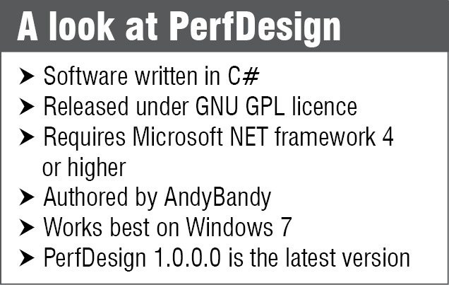
PerfDesign has been completely created using C# and released under GNU GPL licence. There are a few other tools that let you create designs on strip boards like Stripboard Designer, VeeCAD, BlackBoard Circuit Designer, VeroDes and LochMaster, to name a few.
Download latest version of the software: click here
Priya Ravindran is M.Sc (electronics) from VIT University, Vellore, Tamil Nadu. She loves to explore new avenues and is passionate about writing