


A Windows-based shareware for the simulation of PIC microcontrollers. It provides users with a powerful, easy-to-operate and quick processing environment
Anagha P.
PIC Simulator IDE is a powerful tool that assists simulation of PIC family of microcontrollers. It provides developers with a rather simple, comprehensive, user-friendly graphical user interface (GUI) for Windows. This tool also provides users with features such as integrated simulator (emulator), Basic compiler, assembler, disassembler and debugger.
Currently, this program offers full support to the 57 microcontrollers from Microchip’s PICmicro 10F, 12F and 16F series. These models are listed in the table on page III. Some of the microcontroller models are provided with only limited support. It does not back some high-level functionalities such as AllDigital, Adcin, Read, Write, Hseropen, Hserout, Hserin, Hserget, Count, PWMon, PWMduty and PWMoff statements. But all the other basic compiler elements are fully supported. Another limitation is that, only Digital I/O is simulated for these models. The microcontrollers with limited support are listed in the table.
Features
The main simulation interface of the program shows the internal architecture of microcontroller. It has several functionalities such as EEPROM data memory editor, FLASH program memory editor, hardware stack viewer, variable simulation rate, simulation statistics, PIC assembler, an interactive assembler editor for beginners, PIC disassembler and configuration bits editor.

The powerful PIC Basic compiler with smart Basic source editor features the three basic integer data types (1-bit, 1-byte and 2-byte), and optional 4-byte that supports 32-bit arithmetic. The program bundles various simulation modules and interfaces, and also offers support for external simulation modules. It provides breakpoints manager for code debugging, along with breakpoints support.
PIC Simulator IDE is provided with PC’s serial port terminal for proper communication with real devices connected to serial port. It has extensive program options, and even colour themes to customise the appearance. All these factors make this tool simple, interesting and user-friendly.
Installation
Windows Vista, Windows 7 and Windows 8 users: After installing the setup file picsimulatoridesetup696.exe, when you run the program for the first time, right-click on the application shortcut in Windows Start menu (or on the executable file picsimulatoride.exe) and choose the option Run as administrator. Else, an error message would be displayed, which reads: Unexpected error; quitting.
This needs to be done only for the first time the program is opened. From next time onwards, the file can be opened as normal by clicking the shortcut in Start menu or double-clicking the program file using left mouse button and the program gets launched.
The default storage location of program files is the PIC Simulation IDE subfolder in Program Files folder. Some example files to work with are stored in this subfolder. Modifying these files requires admin rights, without which the error message “Run-time error ‘75’: Path/File access error” appears. It also contains three manuals for the users: for getting started, compiler reference and for external modules. Modifying files stored in Program Files folder requires admin rights.
To permanently set the program to run with administrator privileges, right-click on the program icon, select Properties, click on the button Advanced and tick the Run as administrator check box. Administrator rights are not required if the project files are stored in a user private folder (for example: My Documents.)
Getting started
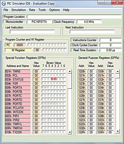
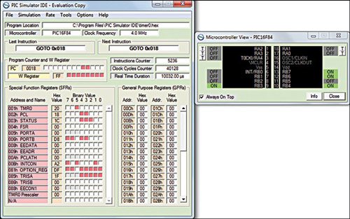
The main window (refer Fig. 1) shows the location of the program being executed, name of the PIC selected, clock frequency, mnemonics of the instruction last executed and the one about to be executed, instructions and clock cycles counter, real-time duration of the simulation and the statuses of internal registers.
The File menu has options to load a program to the PIC memory, clear memory and save memory. From the Simulation menu, you can start or stop a simulation, execute the next step of simulation (when Step By Step simulation rate is selected), or run to the next Basic statement for programs generated by integrated Basic compiler. The user can set the simulation rate to Step By Step, Slow, Normal, Fast, Extremely Fast, and Ultimate from Rate option in the menu bar.
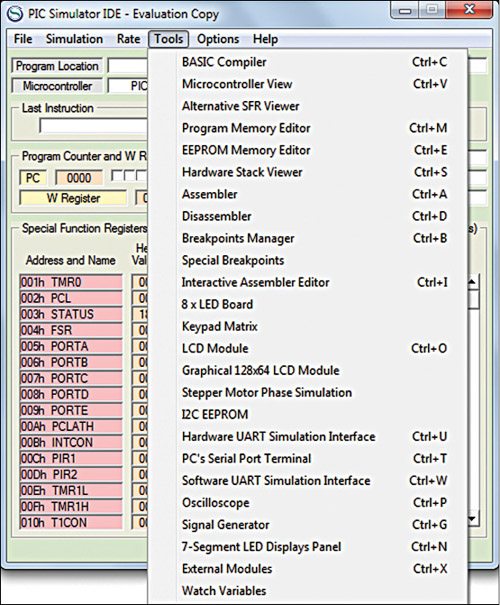
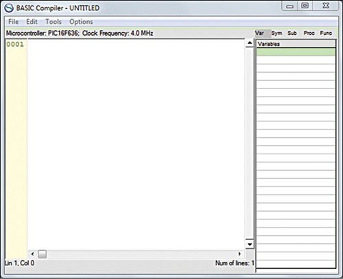
 The Tools option (Fig. 2) gives a variety of modules and interfaces to choose from. Basic compiler opens the integrated Basic compiler editor window, as shown in Fig. 3. The Basic Compiler Reference Manual in Help menu of main window (or Options of Basic compiler editor window) contains more information on this module.
The Assembler command starts integrated assembler. In this window, the assembler source files can be edited and assembled. A similar Disassembler option starts disassembling automatically when this option is selected. Once the operation is complete, the output file is displayed and the user is prompted to save it.
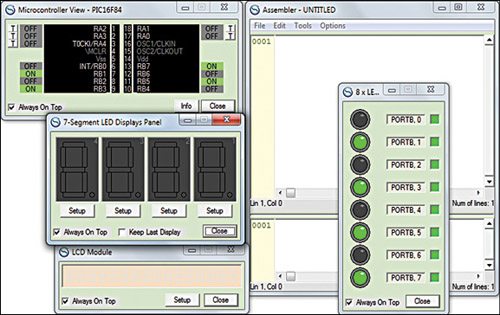
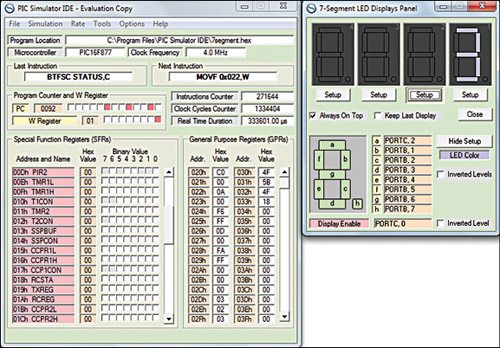
Other main modules and interfaces include Microcontroller View, EEPROM Memory Editor, 8 x LED Board, 7-Segment LED Displays Panel, Stepper Motor Phase Simulator, Oscilloscope, Signal Generator, LCD Module, etc. Fig. 4 shows the screenshot of some of these modules.
