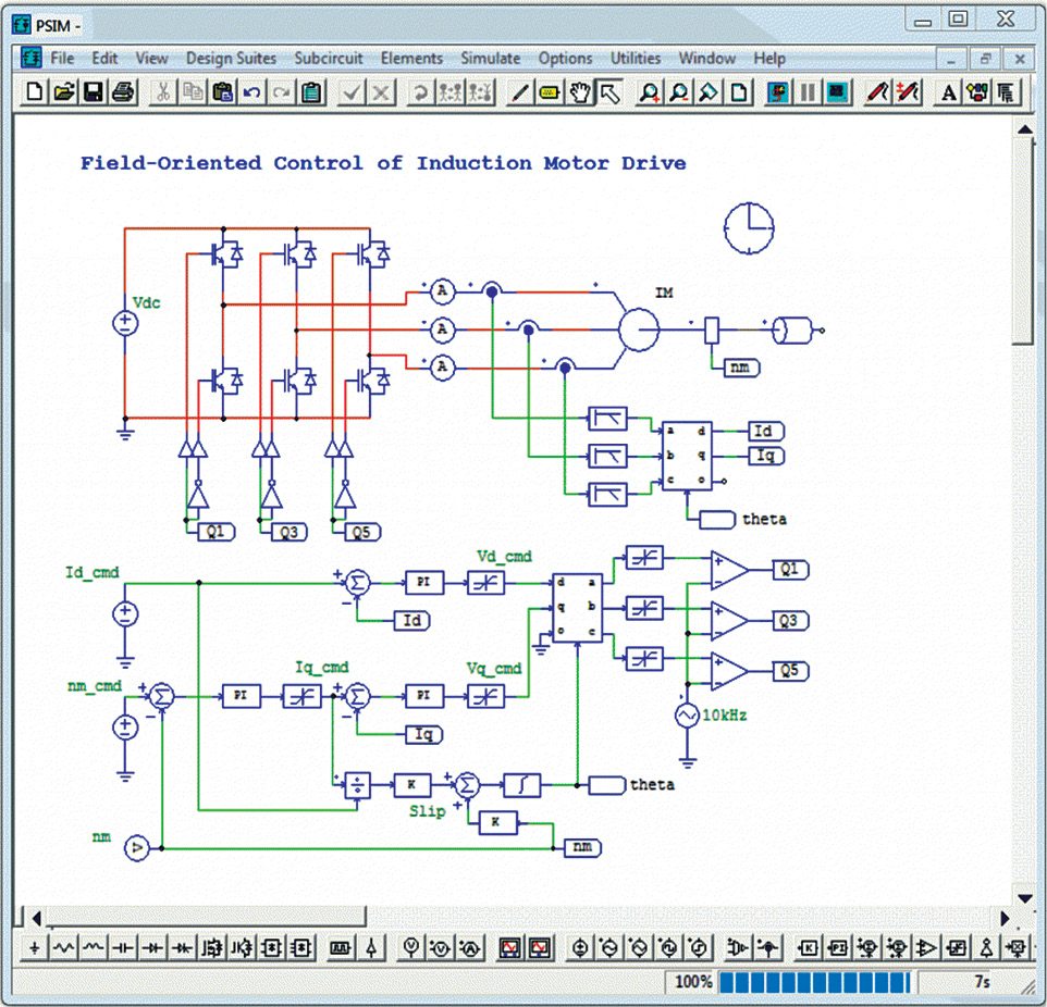
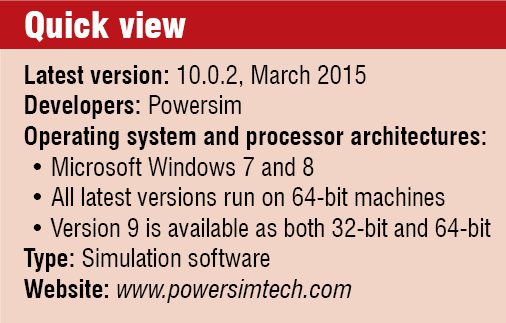
In this article we will discuss about PSIM, a fast, yet accurate, simulation environment for power electronic designs, motor drive simulations and energy-conversion applications. The software is positioned midway between a SPICE-like device or circuit simulator and a system or control simulator like MATLAB or Simulink. PSIM enables the user to build circuits and obtain results easily even without any previous experience of using computer aided design (CAD) software.
The software is widely used in industry for research and development of new products, while academicians use it for research and teaching.

Why PSIM
 This software allows designers to simulate power circuits with any level of detail. The initial version of PSIM was originally released with ideal components only. In the newer version there are only a limited number of equations to be solved, and hence the speed of simulation could be fast.
Simulating power circuits of varying complexities. With the latest version of PSIM it is now very easy to selectively introduce parasitic interactions and non-idealities. This is the key as it allows you to introduce more complex problems as you are ready to solve these, as opposed to how some simulation packages force you to deal with complex issues before you have even settled on major specifications.
PSIM is considered among the fastest simulation environments. It uses a strong algorithm dedicated to electrical circuits (piecewise method, generic models and fixed time-step). The fast simulation allows repetitive simulation runs and significantly shortens the design cycle.
There is no learning curve; one can build circuits in PSIM and start seeing waveforms in minutes. In addition, with a robust solver, PSIM has no convergence issues that other simulation software face.
Easy modelling. There are a lot of modelling options available in PSIM. With the help of some add-on modules, designers can simulate the control circuitry with op-amps, s-domain blocks, in the discrete z-domain or with the embedded runtime C compiler. The frequency analysis of a topology preserves the switching behaviour; there are non-average models used, so non-linear aspects can be accurately measured.
Also, there are a lot of application-specific add-on modules for the model. By using modules for motor drives, digital signal processor (DSP) and field programmable gate array (FPGA) support and renewable energy, we can adapt the models to suit various applications. PSIM can also handle magnetic simulation where users can build custom magnetic circuits with non-linear cores that exhibit hysteresis.
Co-simulation with other environments. SimCoupler module can facilitate co-simulation by providing an interface between PSIM and MATLAB/Simulink. We can thus implement a part of the system using PSIM and the rest using MATLAB/Simulink.
The set up and simulation time of systems is greatly reduced by allowing MATLAB/Simulink users to implement and simulate power circuits in their original circuit form using SimCoupler module. Power electronic researchers can also benefit from this facility by simulating the control in MATLAB/Simulink environment.
PSIM can co-simulate with ModelSim, using PSIM’s ModCoupler module, for VHDL and Verilog code verification. If a user defines a control scheme with z-domain blocks, PSIM’s SimCoder module can translate that algorithm into C code, and with a few additional blocks one can also generate a code that will run directly on a supported DSP with no additional coding steps.
What is new in PSIM 10
A lot of new features have been included in the latest version of PSIM. Let us go through some of these.
Diode model with reverse recovery. PSIM 10 comes with a diode model with reverse recovery. The designer can simulate the diode turn-off process and help predict switching phenomena caused by the diode reverse recovery using this model.
Also, there is provision for the MOSFET model with turn-on/turn-off switching transient. With the help of this model, a developer can easily simulate the switching transient and design the gate drive circuit.
New multisine AC sweep method. This version of the software has adopted a new AC sweep method. It is based on multisine algorithm. In majority of cases, this method gives excellent results in comparison with earlier methods.
Multi-level modelling. The developer might require different levels of models at various stages of simulation. The multi-level modelling feature incorporated in the latest version of this software allows the user to easily switch from one level of model to another by just changing a flag, without changing the schematic. This is a great advantage for the simulation process.
Inclusion of IC models. In order to facilitate the user, a lot of IC models have been included to the standard PSIM library. These include 555 timer, UC3823, UC3825, UC3842/3843, UC3844/3845, UC3846, UC3854, UC3872, UCC3806, UCC3817/3818, UCC3895 and UCC28070.
Besides, there are many interesting features like the ultracapasitor model in the renewable energy module, two solar cell models for crystalline silicon and thin film based on European standard EN50530 and a lot more.


I want this simulation for BLDC motor control. please help me. my email id is sachinkanha610@gmail.com
I want this simulation and schematics for BLDC motor control for 24V@4A rating. please help me.
I want the simulation of MPPT tracking in photvolaic system
I want this simulation and schematics for control Semi-Active Rectifier for Constant Voltage
help me: nhs19051997@gmail.com