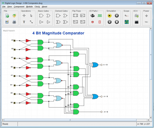
Whether you are a professional, hobbyist or a student, here is free standalone software that helps you design and simulate digital circuits with a huge array of inbuilt components ranging from simple gates to Arithmetic Logic Unit and State Machine. Plus, it includes the testing feature via a simulated oscilloscope!
Circuit design and simulation tools have become an intricate part of an electronics engineer’s life. There are so many such intuitive tools to look through that can help improve designs, shorten design times and lower costs. Digital logic design is one such software which includes many useful features and offers a variety of components for designing and simulating digital circuits.
Key Facts
License: Free
Platform: Windows
Download page: Click here
File Size: RAR 4.x archive, unpacked size 548,984 bytes

Components
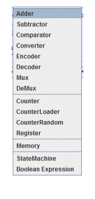
The various components available to you to design and simplify circuits include:
- Basic Gates (Logical AND, Logical OR and Logical NOT)

- derived gates (Logical NAND, Logical NOR and Logical XOR and Logical XNOR)
- flip-flops
- basic Input / Output (I/O) parts (button, clock, LED or light-emitting diode, SSD or seven segment display)
- advanced I/O parts (7-Bits ASCII Keypad as Input Part and CRT Display to display 7-Bits ASCII data and characters)
- power parts
- digital oscilloscope and its probe to monitor digital signals at various multiple points in the circuit during simulation
Component Menu offers all available standard parts or component, other than that available in the Tool Bar, which can be customized and used for circuit designing. A component may have a number of parameters, like name and id number, which may be set by using component context or drop down menu in a circuit drawing. This menu appears when a component is right-clicked with the mouse. Components may have different parameters depending upon their type.
Applications
This software can be used by professionals, students, hobbyists as well as teachers. You can design combinational, synchronous and asynchronous sequential circuits. It can be used by teachers to teach Digital Logic, Computer Architecture, Computer Organisation, Embedded Systems, etc.
Making Module or Custom Parts or ICs
One of the important features of this software is that you can convert any circuit into a reusable Module and use it in any other circuit. A Module can be used to build more complex circuits like CPU and they behave like ICs in a circuit.
Converting a circuit into a Module
To use the Module option, go to File menu and select the To Module Option. Enter Module name in save Module dialog. A new module will be generated. When you open Module menu in the Menu Bar, you will see that your module name appears. This module can be placed in the drawing for use in the same circuit or any other circuit also.
All the Modules which are placed in /Module folder will appear in Module menu of the program. The Modules which are stored in any other folder can be access using “Load” option in Module menu.
If a module is used more than one time in a circuit, all these instances of a module behave as standalone and separate parts. Any change in one instance does not affect any other instance of same module. Therefore, the already used instances of a module will not be affected if the module design is changed later.
Simulation
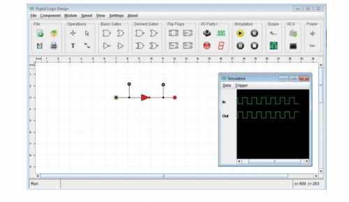
After completing a circuit, you can run the simulation to check the working of the circuit. In simulation you may change or enter values in your circuit through input parts and observe the behavior of your circuit through output parts or on a digital Oscilloscope provided in this software. After running the simulation, you can save the data in a file for later view using Menu in this Scope window Data->Save. The design is saved as .dwg file.
The buttons associated with the simulation of any circuit include: Run the simulation, Stop the simulation, Pause and Resume the simulation and Single Step on every press of this button.
Simulation Modes
This software allows the simulation to be run in two modes: Data-Change Mode and Real-Time Mode. These modes can be enabled by selecting or deselecting the “Global Clock” options in the Clock menu of the software. Selecting this option will enable Real-Time mode while de-selecting this option selects Data-Change mode.
Data-Change Mode: In this mode, whenever there is some data value changes, by pressing a button or from the clock component, the simulation will process all the parts to the new state. If there is no data change, no more processing will be done. In this mode, if you are observing the data changes in a digital oscilloscope, the data signals are only updated when there is some data change in the circuit.
Real-Time Mode: In this mode, the simulation keeps on running whether there is some data change or not. In this case, if you are observing the data changes in a digital oscilloscope, the data signals are continuously updated and appearing on the display showing the current status of the signals in real-time.
Digital Scope
You may need to monitor the signal level at one or different points in a circuit during running of the circuit. For this, the Digital Oscilloscope or Scope works in combination with the probe. The probe marks the places where the signal level needs to be monitored.
How to use the Digital Scope:
Open an already designed circuit or design the circuit. Then decide about the points where you want to monitor the signal level in the circuit during its operation. You can click the “Probe” icon in the “Scope” tool box in the tool bar at the top of the window. When you move to the drawing area, the cursor will change its shape to a Black circle. When you click the mouse near the place where you want to monitor the signal level, a back Circle is placed at that place. In the same way, the probe can be placed at all the places.

Each Probe drop-down menu is used to assign names and Id number to each “Probe” marking. This number is according to the order in which you want them to appear in the “Scope” display. Clicking the “Scope” icon opens up a new Scope Window that shows all the signal names assigned to the “Probe” marking and as per their assigned number value in ascending order. When you run the simulation, all the signal information will start displaying in the Scope window. The scope data can be saved by selecting menu Data->Save Data. You can also set that at which value the scope “Start recording the data”, “Stop recording the data”, and “How many values” it must record before stop recording and displaying the signal information. These settings are available in the “Trigger” menu of the simulation window.
Pros and Cons
Pros:
- An easy and educational software for beginners
- It is free to download
- In this software, a circuit can not only be designed by using graphical components but also by providing values for Boolean Sum-of-Product
- A circuit can easily be converted into a reusable Module to make more complex circuits, like CPU
- To study behavior more appropriately, the design can be executed to update data signals in real-time or whenever there is some data change in the circuit.
Cons:
- Cannot be used for AMS or analog and mixed-signal circuits
- Requires a PC or laptop
For reading other similar reviews: click here
This article was published on 21 December 2021, and recently updated on 12 November 2024.


