The military and aerospace sectors lay down extremely rigid specifications for the designs, going for nothing but the best design practices and only the most precise instruments. Simulation is therefore integral to military and aerospace products design cycle. Here we look at the advantages Saber brings to the design engineers working in the military and aerospace domains
Ashwin Gopinath
As even more electronic equipment get added to the aeroplane electrical systems, the complexities of the end system get more challenging. The addition of these non-linear loads results in a number of power-quality problems when the system is fully integrated. These disturbances include excessive harmonic distortion, voltage sags, transient voltages outside specified limits and power transfer problems.

Use of power electronics for small, low-cost and efficient power supplies has become ubiquitous in commercial applications. A significant disadvantage of power electronic supplies is the non-sinusoidal currents that the equipment draw out of the electrical power system. These harmonic currents interact with the system source impedance resulting in harmonic voltages at the terminals of aircraft utilisation equipment.
Aircraft specifications limit the amount of total harmonic distortion (THD) of the input voltage as well as individual components of harmonic voltage that can exist at the equipment terminals. Typical figures include eight per cent maximum voltage THD and six per cent maximum individual harmonic voltage content.
In recent years, there has been an increase in the use of equipment using switching power supply inputs. This has caused degradation of the voltage waveform with consequent system problems. Many of these problems are not identified until the airplane is fully integrated, when making design changes becomes extremely expensive. In order to maintain acceptable levels of harmonic distortion for the system, limits are imposed on the levels of harmonic currents drawn by different equipment.
Modelling and simulation are used to develop reasonable requirements on the user loads and also to predict system power quality measures, apart from analysing other power quality phenomena such as levels and duration of voltage transients due to load switching and system failures.
Objectives of simulation
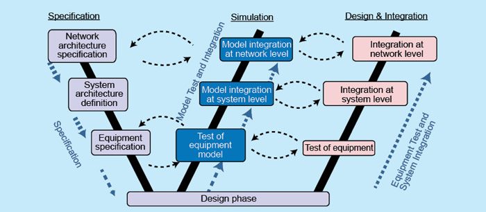
The major role of simulation in the aerospace domain is to conduct design and validation tests on an aircraft’s electrical network taking into account power generation, distribution and network quality studies. From the moment the basic concept is defined to the time of end-of-the definition phase, simulation is crucial in validating every single step on the cycle. Moreover, simulation plays an important role in the studies conducted on power quality and stability of the electrical system in the aircraft. Additionally, it provides invaluable input into the power budget and control/logic studies that are very important from a fiscal point of view.
Simulation also serves to create an accurate replica of the electrical network for an aircraft or any other military installation. The system needs to be able to simulate electrical power generation systems along with the installed switching and protection devices and the power users.
Modelling the systems gives an insight into the accuracy of hardware performances at both the equipment terminal and at the temporal and frequency domain. Simulation also serves to establish the integration at network level between the model library, model interface and solver parameters, thus making the whole process seamless and easier to troubleshoot and maintain.

Several levels of modelling are required to reach the objectives of simulation. In the order of increasing complexity, they would be architectural, functional, behavioural and components. The behavioural model of simulation is used for power-quality study of the network including transient-level voltage, harmonic distortion and voltage ripple. The functional model of simulation mainly deals with the network stability studies along with validation of network configuration logics.
Simulation activity
Functional. The major sources of failure generation at the network level can be narrowed down to the following:
1. Open cable
2. Short circuit
3. Erroneous information signal
4. Contact stuck open or close
5. Power distribution centres
6. Power converters
7. Electric loads
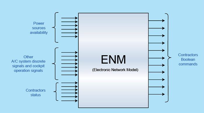
Functional-level modelling aims to integrate voltage generators, power distribution centres, power converters and electric loads and others at the network level to increase the overall system dependability.
Simulation in this modelling follows the following algorithm. The process starts with the construction of a test bench, which is basically a virtual environment used to verify the correctness or soundness of a design or model. The issues that pop up due to the convergence of multi-physics are taken into account and solved as per requirement before the model is simulated. After simulation, post-processing is done. Simulation results include the results of simulating the entire electrical network at a functional level along with finding out the impact of possible failures on the electrical network.
Saber, Synopsys’ simulation tool, offers users the ability to use both analogue and digital solvers to simulate and work on other features while simulating. It also allows users to use other tool models through the ability to import C-code capabilities.


