Symica software suite makes IC design easy and accurate. By including various tools including schematic editor, simulator (using SPICE), waveform viewer and analyser, it provides a complete ecosystem to design and develop electronic systems.
Symica is compatible with Windows and Linux. It comes both as a free edition (FE) and paid version. Unlike full (paid) edition, its free edition does not support mixed-signal setup. However, all the other offerings make up for this drawback.
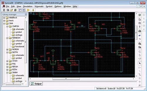
Symica Features
Using schematic editor from Symica DE schematic development environment, designers can access the elements library to choose components and draw the circuit schematic. Other functionalities of the development environment include symbol editor and hierarchy editor. Designers can specify components using the component description format. Symica supports different netlist formats like Spice, LVS, HSpice and Spectre.
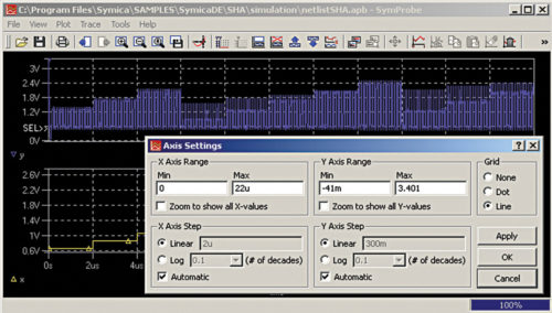
The created schematic is used by the SymSPICE circuit simulator to digitally run the circuit and show its behaviour. Developed by Symica’s in-house R&D team, the SPICE simulation environment supports all industry-format external netlists as well as transistor models. It delivers very accurate simulation signals through a graphical interface. The free edition supports up to 300 elements for simulation and up to ten Verilog-A mode parameters.
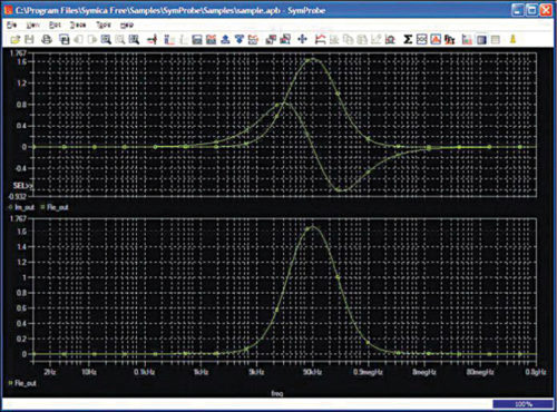
The waveform viewer in Symica, called SymProbe, provides a graphical representation of the simulation waveform. It also helps in simulation result analysis. SymProbe tool provides view of results for DC, AC, SWEEP and TRAN; customisable view of multiple plots; multiple X/Y axes in one plot; and flexible axes adjustment. It can also measure cursor waveforms and brings enhanced printing facility with vector EMF waveform output. Simple drag-and-drop operations make it easy to use. SymProbe accepts input formats like APB, NUTMEG, CSV, CSDF and RAW-SPICE.
In addition, Symica includes a symbol generator for primitive devices (like diodes, transistors and MOS) relevant to the user’s projects and a library translation tool that can import external libraries for use.
As regards feature upgrades, the software now allows current probing for complex transistor models and sub-circuits. There are two modes of probing: direct plot and hierarchical net highlights. Also a project can be shared among distributed design teams.
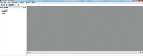
The interface
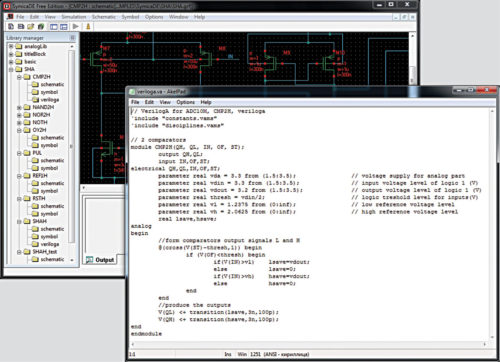
Symica DE features a familiar and easy-to use user interface. It consists of a black dotted workspace, where schematics can be designed using drag-and-drop actions. Users can tweak characteristics of components by right-clicking on them inside the workspace.
The left panel consists of projects, netlists and components. You can either add components to your project or view existing ones by expanding the folders. On the top, there is a menu bar with File, Edit, View, Simulation, Symbol, Options, Window and Help buttons. Below the menu bar, there are some quick-access buttons. One of them resembles ‘play’ symbol. It allows users to start simulation of the built schematic. To the right of the workspace, there are more quick keys. At the bottom, there is a dedicated panel for displaying output results and error messages.
When you turn on simuation, SymSPICE window opens to show signal behaviour of the circuit in graphical format. Menu bar on the top includes Plot, Trace, Tools, View and File options. Below the menu bar, you can find quick buttons for axes property update, plot updates and so on.
Applications
Symica can be used to design, evaluate and analyse system-on-chips, including high-speed multi-bit analogue circuits, analogue-to-digital conversion circuits, digital-to-analogue conversion circuits, phase-locked loops and high-speed controllers. It can be used both for small as well as large-scale projects.
Symica is compatible with Verilog-A codes. With more useful features like parametric cell creation, support for global nets, buses and bundles, and enhanced printing, it is a perfect tool for electronics designers.


