


Apart from increasing the productivity of designers and improving the quality of design, computer-aided design (CAD) software assist in the creation, analysis, modification or optimisation of a design. The major areas where CAD is used are electronic design, mechanical design and engineering drawings. Here is an overview of this software
Abhishek Mutha
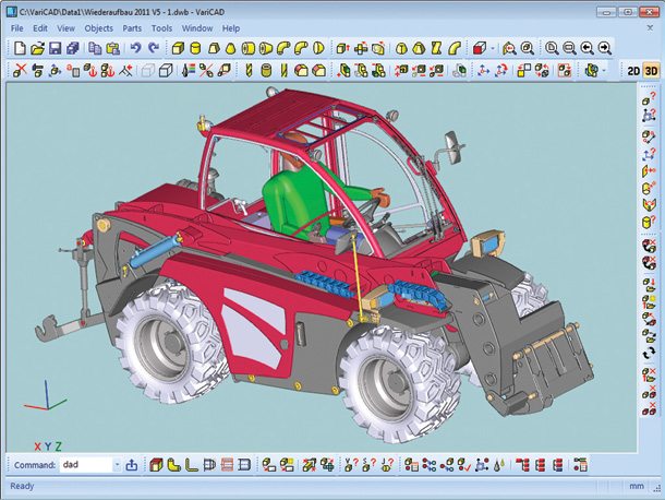
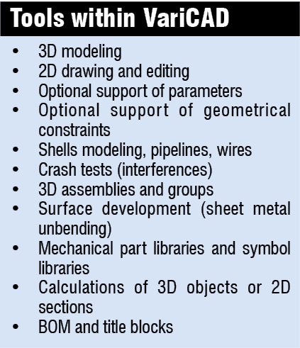
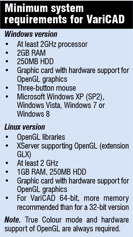
VariCAD is a software for 3D/2D CAD that runs on Windows and Linux. In addition to tools for 3D modelling and 2D drawing-cum-editing, it provides support for geometrical constraints, tools for shells, pipelines, sheet metal unbending and crash tests, and assembly support to name a few. The system contains both 3D and 2D libraries of mechanical parts (DIN and ANSI), hydraulic and electrical symbols, and tolerance symbols as well.
Impressive functionality
VariCAD features a lot of interesting functions that vary from an intuitive user interface (UI) all the way to performing virtual crash tests and creating a bill of materials (BOM).

User interface and system environment. Designed to allow quick and intuitive 3D/2D orientation, VariCAD’s graphical user interface has been carefully tailored and tuned to reflect the thought process of a designer so that ideas can be captured and communicated with a minimal number of steps. The commands have been created with a focus on ease of use.
 It is possible to start by creating a 3D model and then use it to automatically create drawing files, or draw only in 2D. Designing in 3D is generally more natural since it closely represents actual parts and assemblies. Hence the 3D approach is usually more intuitive than 2D drafting. Models created in 3D can be easily converted into conventional 2D documentation.
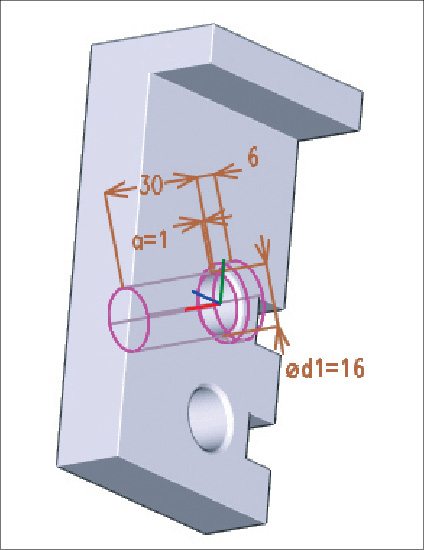
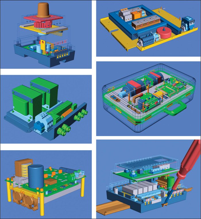
3D modelling. With the help of a library of basic 3D shapes (box, cylinder, cone, etc) that could be easily modified by editing their dimensions, solids can also be created by profile rotation, lofting or extrusion. Tools with higher complexity include rotation blending between two profiles, creation of helical surfaces, and lofting between a circle and rectangle, or between different profiles.
 Addition or subtraction of solids is possible, thus forming Boolean trees representing real mechanical parts. Automatic trimming is available for Boolean operations. Predefined operations like groove milling, face milling or drilling of holes are also available. With an option of rounded or chamfered edges, VariCAD provides a lot of possibilities of solid transformations or their editing. Also, Boolean trees can be easily edited by selecting them from a list displaying the structure, or by selecting solid parts from 3D.
Parameters and geometrical constraints. Solids or their parts can be comfortably transformed, and it is also possible to optionally define geometrical constraints. Once defined, these constraints allow the user to ‘stick’ object at the defined location. Constrained object changes its position automatically if other objects are changed or transformed. For example, if a user constrains a groove to the end of a shaft and the length of the shaft is changed, the groove remains in constant distance from the end edge. Constraints can be defined within a 2D profile creating a solid (for instance, by extrusion), among elements of a solid or among entire solids.
Whenever the user enters a dimension in 2D profile used for solid creation, a distance in constraint or a dimension of solid, it is possible to optionally use parameter or even a mathematical expression containing parameters. One can change shapes or locations of solids by changing parameter values.
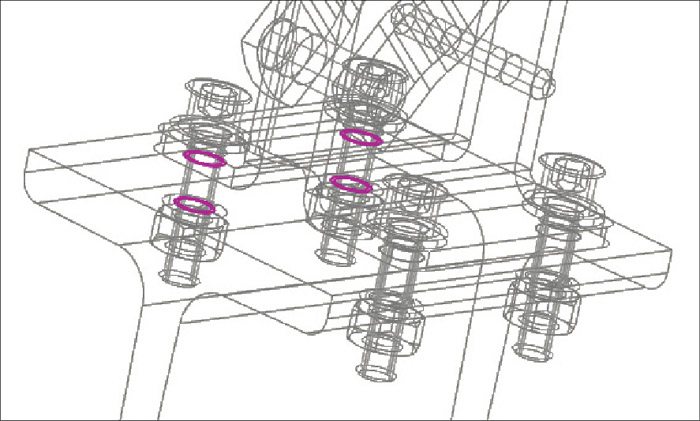
3D assemblies and groups. VariCAD also provides assembly support tools. If the link between a part and assembly is defined, any changes to be made to the part file are reflected in the assembly file and vice-versa. Linked copies of solids (also known as identical solids) can also be defined.
When creating assemblies, it is up to the user whether he wants to use links between the assembly and parts or have all-in-one document. If you decide to use these links, all the changes in assemblies or parts are automatically made also in all the drawings you need.
Crash tests (interferences). Component interference checking is one of the excellent features of 3D modeling. VariCAD can check 3D assemblies for possible collisions (overlapping volume) between components.
Calculations. Moment of inertia, centre of gravity, mass, volume, 2D section area and surface area can be calculated with the help of VariCAD. Mechanical parts calculations are also included for standard parts used everyday by mechanical designers. There are calculations of belt drives, pre-stressed bolted connections, spur, grooved shafts, pins and parallel keys, bearings, tension and compression springs, beams under combined stress (bending and torsion) and bevel gearing geometry.
VariCAD contains many tools for checking the created models. It detects interferences between solids, and checks attributes of the solids so that these are correctly inserted into BOM or your corporate information system.
\


I’m looking for purchase Vericad 3D modelling software.
Request you to provide Bangalore location Dealer .. Contact no.
And also quotation.
Thanks and regards
Nagaraj Saklathi G.