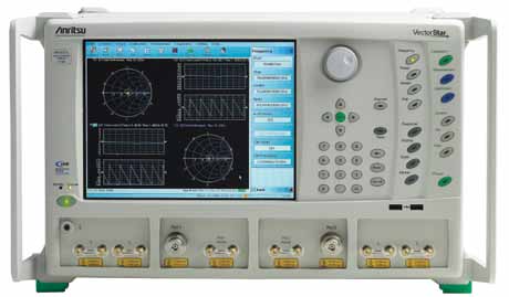
Vector network analyser. Network analyser is a popular solution for test and measurement of passive components. It is used to measure the network parameters of electrical networks.
In today’s world, network analysers commonly measure s–parameters because at high frequencies, the reflectionand transmission of electrical networks are easy to measure. Network analysers are often used with two-port networks to characterise their parameters, but they can be used on networks with an arbitrary number of ports as well.
A vector network analyser (VNA) is a sub-type of a network analyser alongside the scalar network analyser (SNA). A VNA differs from an SNA as an SNA measures only the amplitude properties, whereas a VNA measures both amplitude and phase properties. A VNA may also be called a gainphase meter or an automatic network analyser.

“Once a passive or active component has been designed using the total measurement capability of a VNA, an SNA may be a more cost-effective measurement tool for the production line to reveal out-of-specification components. While SNAs require an external or internal sweeping signal source and signal separation hardware, they only need simple amplitude-only detectors, rather than complex (and more expensive) phase-coherent detectors,”—explains application note 1291-1B by Agilent Technologies.
[stextbox id=”info”]
What is quite important, yet compromised even today is ensuring some of the key attributes, viz, reliability, performance, maintainability, supportability, usability and performance, that end users are looking for in addition to low-cost components”
— Anjaneya Vara Prasad Gundu, head of process management, Cigniti Technologies
[/stextbox]
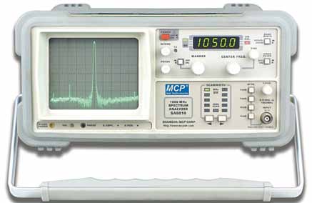
Spectrum analyser. A spectrum analyser measures the magnitude of an input signal versus the frequency within the full frequency range of the instrument. The primary function of the analyser is to measure the spectral power of known and unknown signals. By analysing the spectra of the inputted electrical signals, dominant frequency, distortion, power, bandwidth, harmonics and other spectral components of a signal can be observed, which are not easily detectable in waveforms based on time-domain responses. These parameters are useful in the characterisation of electronic devices, passive and otherwise.
Spectrum analysers are among the most essential of RF/microwave instruments, showing in the frequency domain what a high-speed oscilloscope might show in the time domain, hence having the capability to reveal a great deal about the performance of a system and its components.
By adjusting the settings of a spectrum or signal analyser, such as the RBW filter, the measurement accuracy can be optimised. A narrow RBW filte can make it possible to display low-level signals at the expense of sweep speed. However, if RBW filter are too narrow, sideband information for signals with wideband modulation may be lost. Additional passive components in a test setup, such as coaxial cables and external filters, also serve t infuence the measurement accuracy of a spectrum analyser.
Newer spectrum analysers allow users to store the amplitude response of different passive components and measurement setups so that calibration is not necessary every time the test setup is used.
Challenges to navigate
Use of passive devices in low-voltage applications is increasingly becoming common. Laptops and cell phones require batteries with ultra-low internal resistance. So manufacturers and users of passive components are now starting to pay greater attention to the materials and processes used to build them, as well as the new rules about using them in low-voltage applications.

Thermoelectric EMFs are very common in passive components constructed of dissimilar materials, such as resistors. Design and manufacturing activities, such as testing batteries with ionic resistance, demand greater focus regarding the impact of noise and thermoelectric EMFs on measurement accuracy. This can be particularly challenging because very low test currents are required to measure these single milli-ohm resistances.
Understanding the challenges of using passive components in low-voltage circuits, the sources of error, and proper means for characterising them is extremely crucial to the proper design of low-voltage devices.
Commenting on the challenges faced by T&M engineers, T. Anand says, “One of the major challenges we face these days is ‘testing capability for quantity’. Most customers would not prefer to buy too many T&M equipment as their test quantum increases. They usually expect T&M solution to be capable of handling a large number of component tests that can be done faster. For instance, one of our existing customers recently changed their test sample size, which is critical from their quality acceptance perspective. However, this increase in test quantity is leading to demand of shortening test duration without any impact on test functionality and parameters. These types of pressures make the work challenging. T&M solutions must be ready to cater to ever-changing testquantities in future.”
Anjaneya Vara Prasad Gundu adds, “Testing is in high demand and some of the challenges that are hampering the growth include testing being compromised by clients due to overrun in the design and development phases by respective partners, lack of skilled resources with a knowledge of applying their knowledge and the non-integrity of the various measurement tools used during the life cycle.”


